Bionic coupling vibration damper

A shock absorber and steel wire rope technology, which is applied in the field of bionic machinery, can solve the problems of not being able to take into account large shock resistance, vibration and shock resistance, etc., and achieve the effect of small structure, strong versatility, and convenient manufacture

Inactive Publication Date: 2008-11-12
JIANGSU UNIV
View PDF6 Cites 0 Cited by
  • Summary
  • Abstract
  • Description
  • Claims
  • Application Information

AI Technical Summary

Problems solved by technology

[0004] The purpose of the present invention is to solve the technical problem of achieving both resistance to large vibration and shock, and to solve the shortcomings of the existing shock absorber technology that cannot take into account the resistance to large shock or can not take into account the resistance to vibration and shock at all when attenuating vibration. Bionic coupling shock absorber capable of realizing three-way vibration reduction and shock resistance

Method used


Image

  • Bionic coupling vibration damper
  • Bionic coupling vibration damper
  • Bionic coupling vibration damper

Examples


Embodiment Construction

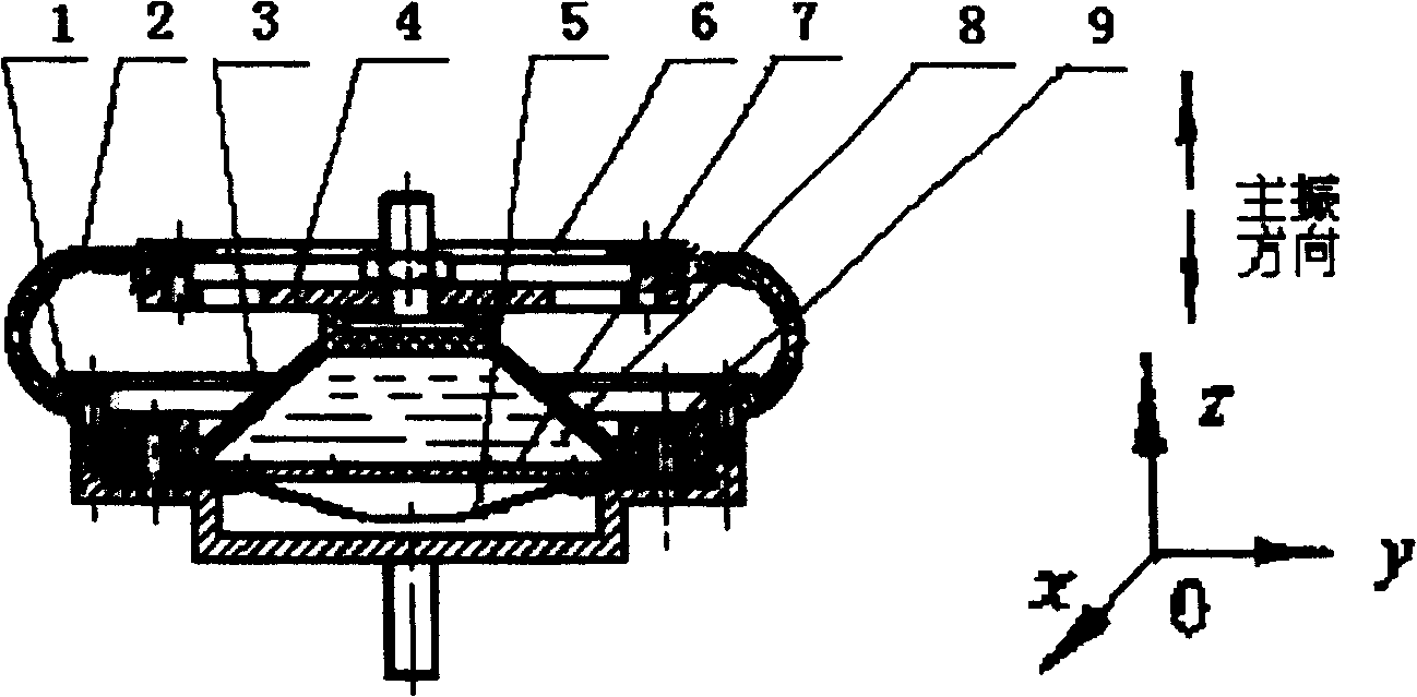
[0017] Such as figure 1 As shown, in Embodiment 1, a number of steel wire ropes 2 are used to form a cover frame structure, generally 3 to 8 strands are used, and the damping plate 7, the rubber cover 3 and the rubber film 5 form the upper and lower chambers for the oil to flow in series, and the rigidity is extremely small. The rubber membrane 5 and the base 1 form an air squeeze chamber, and the oil 8 can generally adopt silicone oil. In this way, the material and structure are coupled to form a physical structure similar to the characteristics of the head and neck of a woodpecker, so as to achieve bionic anti-vibration by utilizing the superior vibration damping performance of steel wire rope, the superior shock resistance performance of oil damping and the nonlinear adjustment characteristics of air extrusion The goal of the impact protection function.

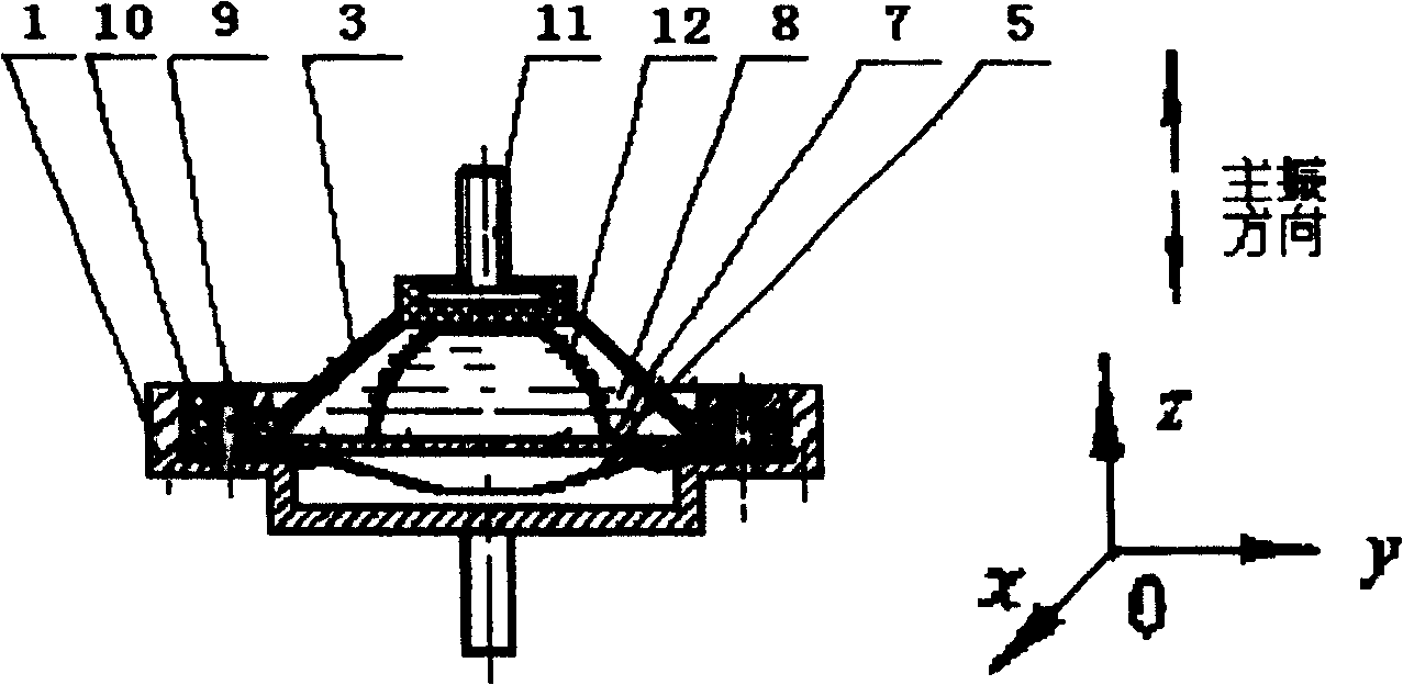
[0018] Such as figure 2 As shown, embodiment 2 adopts several steel wire ropes to form the crown-shaped cover frame s...


PUM


Abstract

A bionic coupled vibration damper is coupled up via wire ropes(gauzes), oil liquid, air, a damping plate, a rubber cover, a rubber film and a base. A screen frame structure is formed by several strands of wire ropes or wire gauzes. Oil-flowing upper and lower cavities are formed via the damping plate, the rubber cover and the rubber film. An air-extruding cavity is formed via the rubber film and the base.

Description

technical field [0001] The invention relates to bionic machinery, in particular to a bionic coupling shock absorber used for anti-vibration shock protection. Background technique [0002] The excitation and coupling of various random factors such as vibration and shock under different working conditions form an extremely complex dynamic environment, which has become an important factor restricting the reliability and motion stability of various equipment. For a long time, people have been committed to vibration reduction Theoretical and technical studies of buffering. Current technical problems: When the existing shock absorber technology attenuates vibration, it cannot take into account the resistance to large shocks or shocks at all, and cannot realize the function of three-way vibration reduction and shock resistance. [0003] In recent decades, with the high development of science and technology, new vibration theories, testing techniques, and new anti-vibration and sho...

Claims


Application Information

Patent Timeline
Patent Type & Authority Patents(China)
IPC IPC(8): F16F9/06
Inventor 杨平
Owner JIANGSU UNIV
Why Eureka
Try Eureka