Movement guiding device, table device, and damping method for movement guiding device

A guide device and workbench technology, applied in the direction of linear motion bearings, bearings, shafts and bearings, etc., to achieve the effects of improved oil retention characteristics, low load, and reduced vibration

Inactive Publication Date: 2009-09-30
THK CO LTD
View PDF7 Cites 0 Cited by
  • Summary
  • Abstract
  • Description
  • Claims
  • Application Information

AI Technical Summary

Problems solved by technology

However, conversely, the disadvantage is that since the sliding guide does not generate damping force such as frictional resistance, once vibration occurs, it is difficult to dampen it

Method used


Image

  • Movement guiding device, table device, and damping method for movement guiding device
  • Movement guiding device, table device, and damping method for movement guiding device
  • Movement guiding device, table device, and damping method for movement guiding device

Examples


Embodiment

[0113] The following mathematical formula 1 shows a formula for calculating the viscosity resistance of oil. Figure 22 is a schematic diagram showing parameters used in this calculation formula.

[0114] [Number 1]

[0115] γ(1 / s)=V(m / s) / h(m)

[0116] τ(Pa)=F(N) / A(m 2 )

[0117] η(Pa·s)=τ(Pa) / γ(1 / s)

[0118] ε(mm 2 / s)=η(Pa·s) / 10 3 / ρ(g / cm 3 )

[0119] thus

[0120] F(N)=η(Pa·s)·A(m 2 )·V(m / s) / h(m)

[0121] =ε(mm 2 / s) ρ(g / cm 3 )·A(m 2 )·V(m / s)·10 3 / h(m)

[0122] γ: Cutting speed

[0123] V: speed

[0124] h: height

[0125] τ: Shear stress

[0126] F: Viscous resistance

[0127] A: Contact area

[0128] η: viscosity

[0129] ε: Kinematic viscosity

[0130] ρ: density

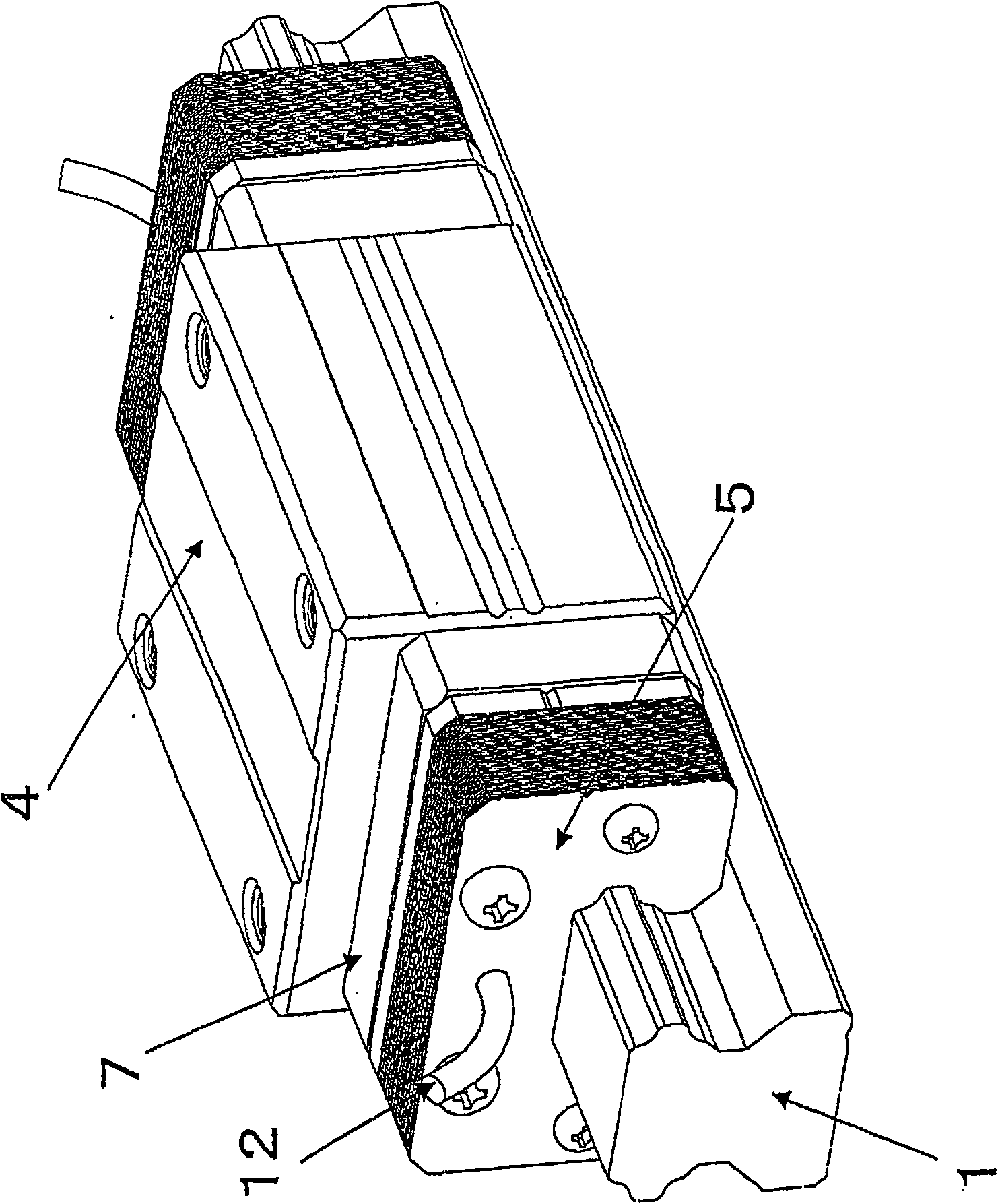
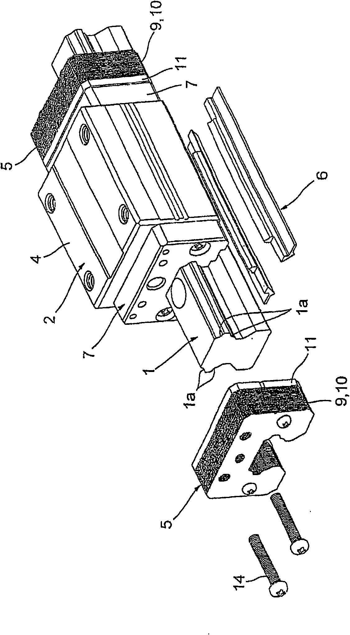
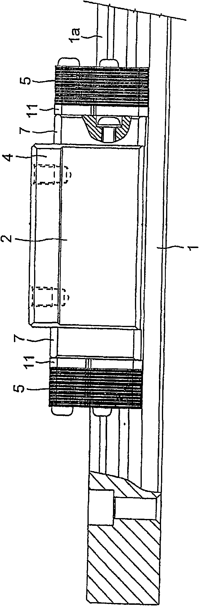
[0131] One parameter of the viscous resistance F is the velocity V. The faster the moving part 2 moves, the greater the viscous resistance F. The height h is the height of the oil layer, that is, the size of the gap 16 between the end damping member 5 and the rail guide 1 . The narr...


PUM


Abstract

The present invention provides a motion guide device with a novel shock absorbing structure different from conventional shock absorbing structures. The present invention is provided with a track component (1) having a rolling element rolling portion (1a), having a load rolling element rolling portion (2a) opposite to the rolling element rolling portion (1a) and relative to the track component (1 ) the moving part (2) capable of relatively linear or curved motion, and the rolling part (1a) between the rolling part (1a) of the track part (1) and the rolling part (2a) of the moving part (2) Multiple rolling elements (3). The gap (16) between the track part (1) and the moving part (2) is filled with an oil layer that is in contact with the track part (1) and the moving part (2). Using the viscous resistance of the oil, a braking force proportional to the speed is applied to the moving part (2) or the track part (1).

Description

technical field [0001] The invention relates to a motion guide device such as a linear guide rail, a ball spline, a ball screw and the like that make rolling bodies such as balls and rollers interposed between a track member and a moving member. Background technique [0002] Conventionally, the following rolling guide type motion guides are generally used, such as a table that moves linearly on a machine frame, in which rolling elements such as balls or rollers are interposed in the guide portion of a moving object that performs linear motion. The rolling motion of the rolling elements realizes the guiding function. A rolling guide type motion guide device is composed of a rail guide for forming a motion rail of a moving body, a moving block that moves relative to the rail guide, and a rolling element interposed between the rail guide and the moving block. [0003] The advantage of rolling guides compared to sliding guides is that they have very little frictional resistance...

Claims


Application Information

Patent Timeline
Patent Type & Authority Patents(China)
IPC IPC(8): F16C29/06
Inventor 道冈英一芳野雅彦本间光明永井知
Owner THK CO LTD
Why Eureka
Try Eureka