Dip angle type rotary seat

A rotary seat and inclination type technology, applied in the field of rotary seats, can solve the problems of restricting the function and application of ordinary double-head pipe benders, and can not complete the three-dimensional three-dimensional pipe bending of the pipe fittings to be processed at one time, so as to broaden the function and use range and effect of the occasion

Inactive Publication Date: 2008-12-17
JIANGSU HEFENG MECHANICAL MAKING
View PDF8 Cites 0 Cited by
  • Summary
  • Abstract
  • Description
  • Claims
  • Application Information

AI Technical Summary

Problems solved by technology

This form of slewing seat can only make a single slewing motion around the annular T-shaped groove of the adjustment carriage, so that the head in the ordinary double-head pipe bender can only be limited to the two-dimensional horizontal plane for rotating and bending motions, and cannot treat The three-dimensional three-dimensional bending of pipe fittings is completed at one time, which restricts the further expansion of the functions and application occasions of ordinary double-head pipe bending machines

Method used


Image

  • Dip angle type rotary seat
  • Dip angle type rotary seat
  • Dip angle type rotary seat

Examples


Embodiment Construction

[0016] The present invention will be further described below in conjunction with the accompanying drawings, but the present invention should not be limited to this embodiment.

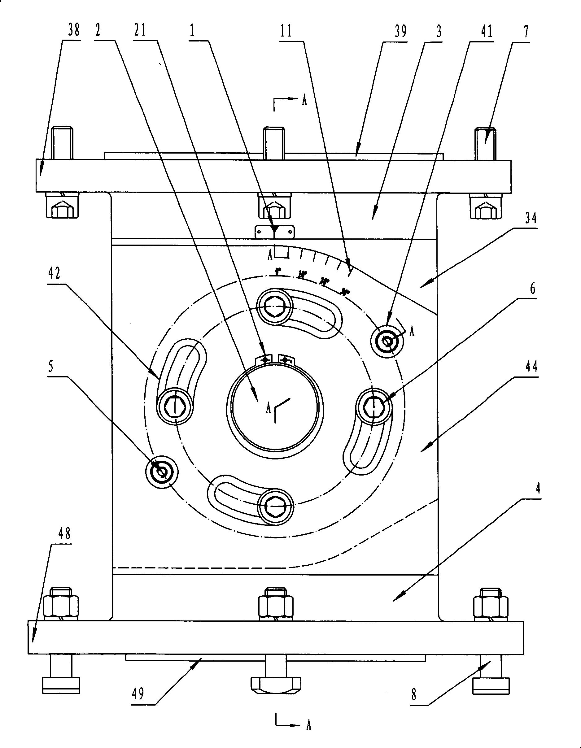
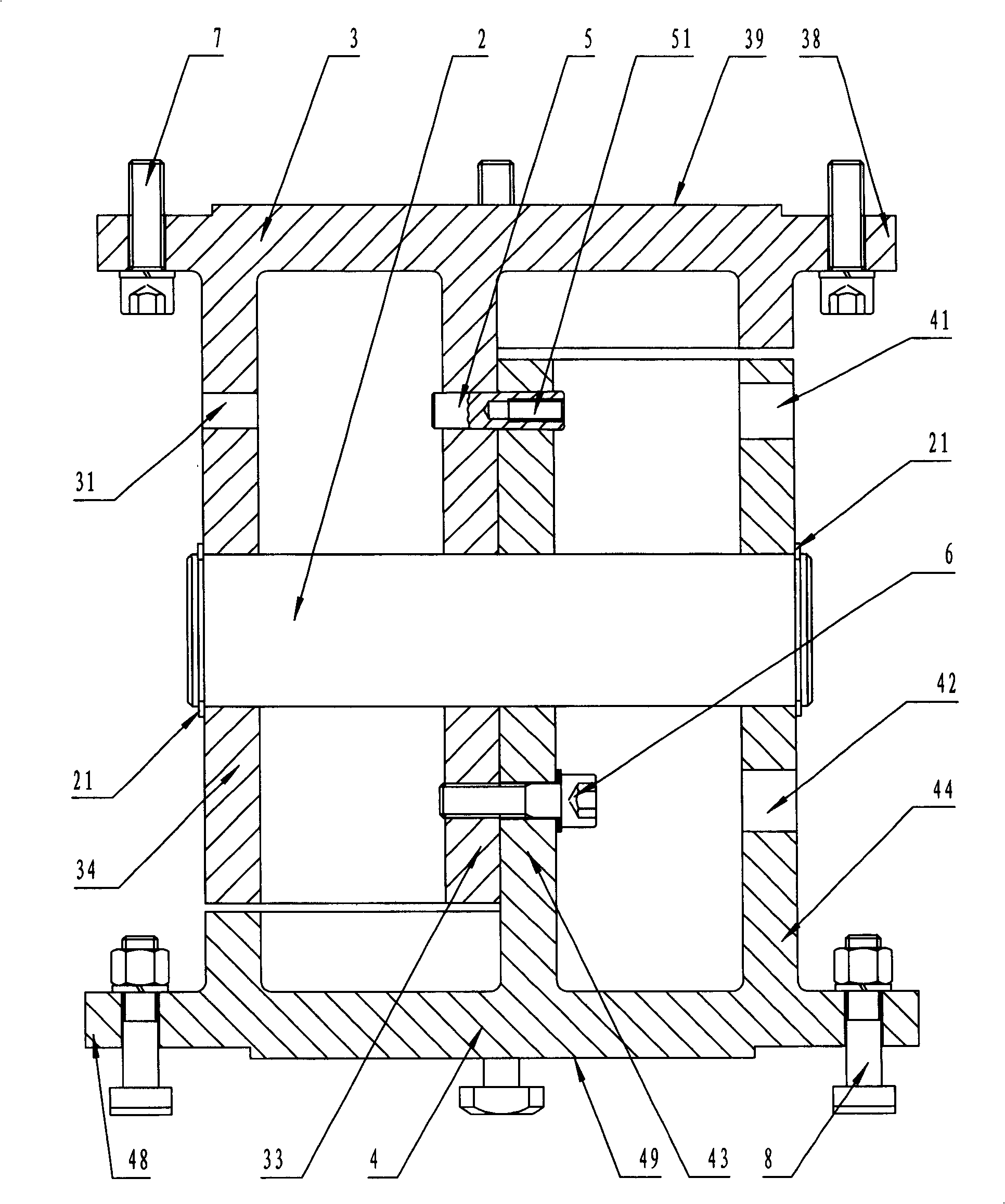
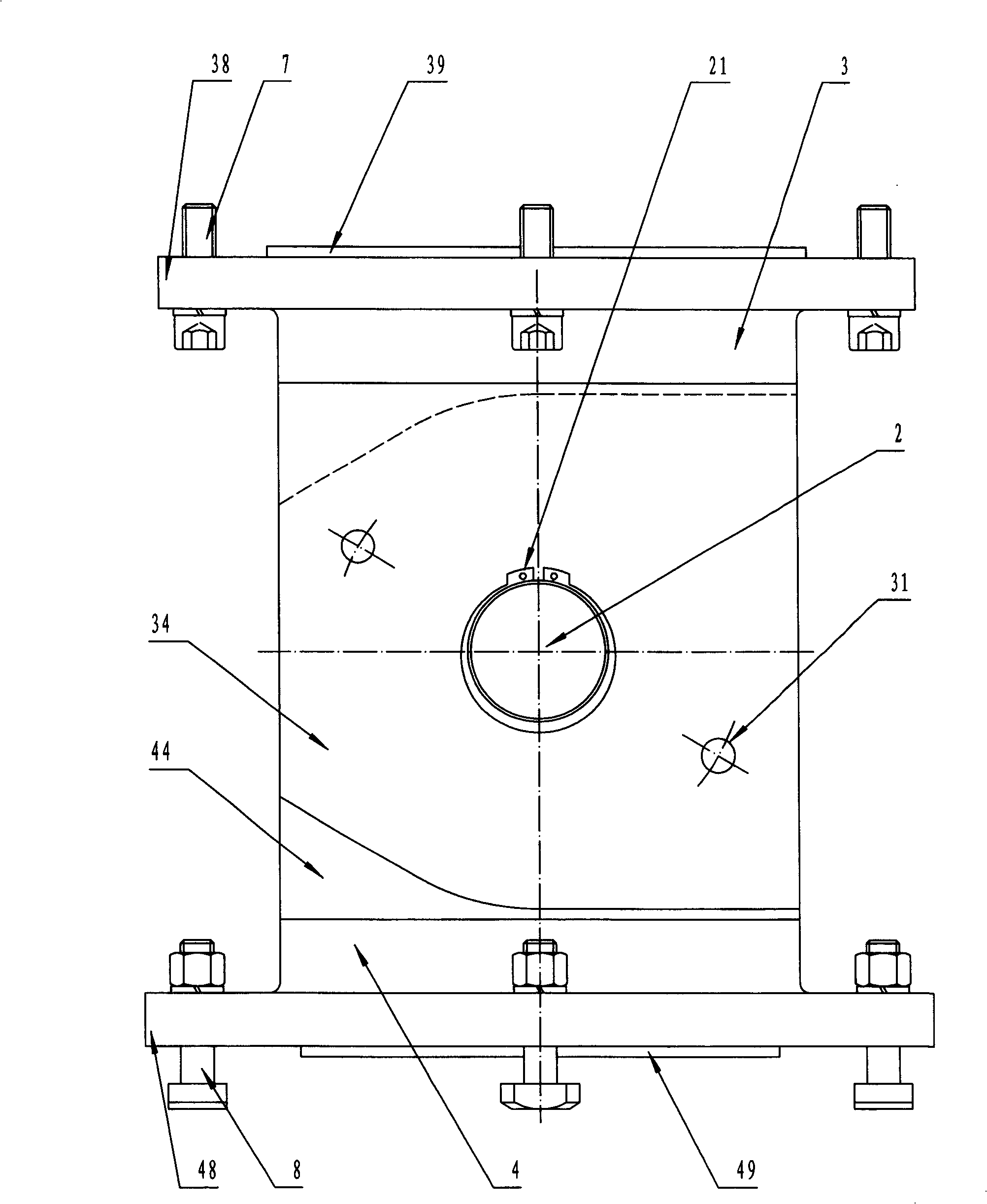
[0017] Such as figure 1 , figure 2 , image 3 As shown, the tilt-type rotary seat of the present invention includes: a rotary body hinged together by the upper seat 3 and the lower seat 4 through the center pin shaft 2, and its specific connection structure is: the center pin shaft 2 passes through the upper seat 3. The central shaft hole in the lower seat 4 extends out of the upper seat 3 and the lower seat 4. On the center pin shaft 2 close to the corresponding positions on the outer surfaces of the upper and lower seats 3 and 4, there are card slots, and the card slots opened The groove should ensure that there is a small amount of clearance between the upper seat 3 and the lower seat 4, and respectively install a circlip 21 so that the upper and lower seats 3 and 4 can rotate smoothly around th...


PUM


Abstract

The present invention discloses dip angle type revolving seat for bending 3D bent pipe inside one common double-headed pipe bender. The dip angle type revolving seat includes one revolution body comprising one upper seat and one lower seat hinged mutually through one central pin shaft, and one locking device set between the upper seat and the lower seat for locking them. The upper seat and the lower seat can rotate around the pin shaft, and each of the upper surface of the upper seat and the lower surface of the lower seat has assembling side with assembling holes. The common double-headed pipe bender with the dip angle type revolving seat mounted may be used in bending not only 2D bent pipe but also 3D bent pipe.

Description

technical field [0001] The invention relates to a revolving seat used in a pipe bending machine, in particular to a revolving device fixed at the lower part of the head of a double-head pipe bending machine. Background technique [0002] Such as Figure 5 As shown, the revolving seat currently used in ordinary double-head pipe benders usually includes: a hollow revolving body 1, the upper and lower end surfaces of the revolving body 1 are provided with assembly sides 4 and 5, and the upper and lower ends of the revolving body 1 are provided with A number of assembly holes are respectively opened, and the fixing bolts 2 pass through the assembly holes on the assembly side 4 to fix the upper end surface of the rotary body 1 and the machine head in the pipe bender together, and then set the activity on the ring T of the adjusting carriage. T-shaped bolts 3 in the groove pass through the assembly holes on the assembly edge 5 and are fixed together with the lower end surface of t...

Claims


Application Information

Patent Timeline
Patent Type & Authority Patents(China)
IPC IPC(8): B21D7/00B21D7/024
Inventor 林洪才林永才陶志高季爱芬
Owner JIANGSU HEFENG MECHANICAL MAKING
Why Eureka
Try Eureka