
Gas directional radiating device
A technology of directional radiation and radiators, which is applied in the field of directional radiators, can solve the problems of unusable places with high-power power supplies, poor electricity safety, and high cost, and achieve the effects of safe and reliable use, short heating time, and low cost
- Summary
- Abstract
- Description
- Claims
- Application Information
AI Technical Summary
Problems solved by technology
Method used
Image

Examples
specific Embodiment approach 1
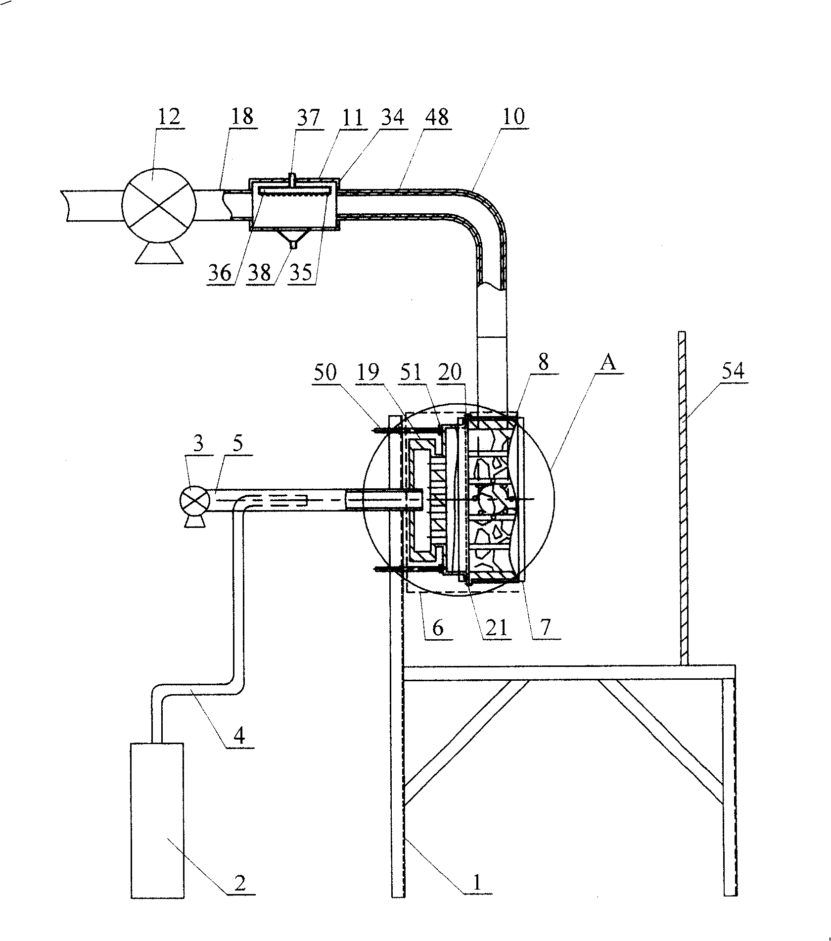
[0006] Specific implementation mode one: combine figure 1 , image 3 and Figure 11 This embodiment is described. This embodiment consists of a bracket 1, a gas bottle 2, a blower 3, a gas pipe 4, a delivery pipe 5, a burner assembly 6, a directional radiation device 7, a flue gas delivery frame 8, and a first flue gas elbow 9. The second flue gas elbow 10, the water spray heat exchanger 11, the induced draft fan 12, the flue gas pipe 18, the bolt 50 and the nut 51; the lower end of the gas pipe 4 is connected to the gas outlet of the gas bottle 2 , the upper end of the gas pipe 4 is installed in the delivery pipe 5 and is matched with the delivery pipe 5, the rear end of the delivery pipe 5 is connected with the air outlet of the blower 3, the front end of the delivery pipe 5 is installed in the burner assembly 6, and the burner The outer end surface of the assembly 6 is fixed with a nut 51, the two ends of the bolt 50 are respectively connected with the nut 51 and the brac...
specific Embodiment approach 2
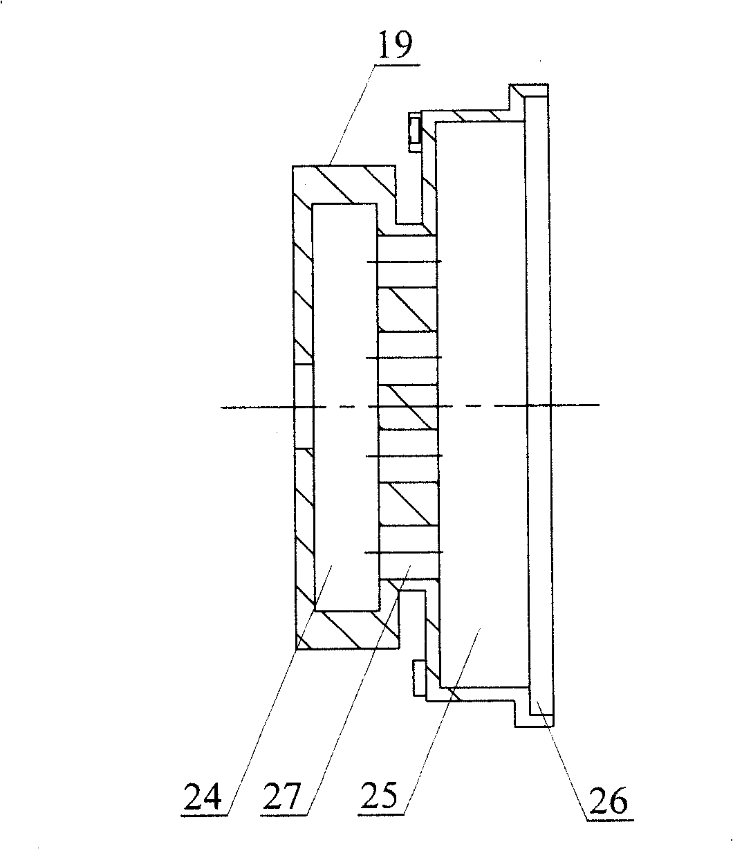
[0007] Specific implementation mode two: combination figure 1 , figure 2 , Figure 4 and Figure 11 To illustrate this embodiment, the burner assembly 6 of this embodiment is composed of a burner 19, a heat insulation frame 20, and a connecting frame 21; the burner 19 is composed of a shell and a solar fire infrared combustion surface layer 23; the shell The body consists of rear air intake chamber 24, connecting channel 27, middle air intake chamber 25 and front shoulder hole 26 in turn; the rear air intake chamber 24 communicates with the middle air intake chamber 25 through a group of connecting passages 27, and the middle air intake chamber 25 communicates with the front shoulder hole 26, the front shoulder hole 26 is fixed with a solar fire infrared combustion surface layer 23, the front end of the delivery pipe 5 is installed in the rear air intake cavity 24, and the heat insulation frame 20 is set in the shell and located at the position of the solar fire infrared c...
specific Embodiment approach 3
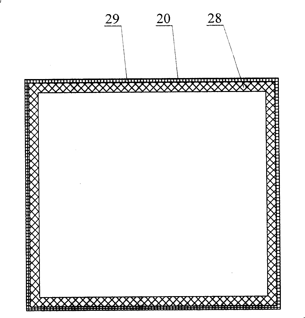
[0008] Specific implementation mode three: combination Figure 4 and Figure 5 To illustrate this embodiment, the heat insulation frame 20 of this embodiment is composed of an aluminum silicate felt insulation layer 28 and a wire mesh frame 29; the inner wall of the wire mesh frame 29 is equipped with an aluminum silicate felt insulation layer 28. So set, can play the effect of thermal insulation to solar fire infrared burning surface layer 23. Other components and connections are the same as those in the second embodiment.
PUM
 Abstract
Description
Claims
Application Information