Vacuum low-temperature ball valve

A technology of vacuum cryogenic and ball valves, which is applied in the direction of valve devices, cocks including cut-off devices, engine components, etc. It can solve the problems of poor heat insulation effect and short service life, and achieve small cold loss, reduce metal heat conduction, and increase heat conduction length. Effect

Inactive Publication Date: 2009-02-11
中国航天科技集团公司第一研究院第一〇一研究所
View PDF8 Cites 1 Cited by
  • Summary
  • Abstract
  • Description
  • Claims
  • Application Information

AI Technical Summary

Problems solved by technology

Cryogenic ball valves mostly adopt stacked insulation layer, which has poor insulation effect and short service life

Method used


Image

  • Vacuum low-temperature ball valve
  • Vacuum low-temperature ball valve
  • Vacuum low-temperature ball valve

Examples


Embodiment Construction

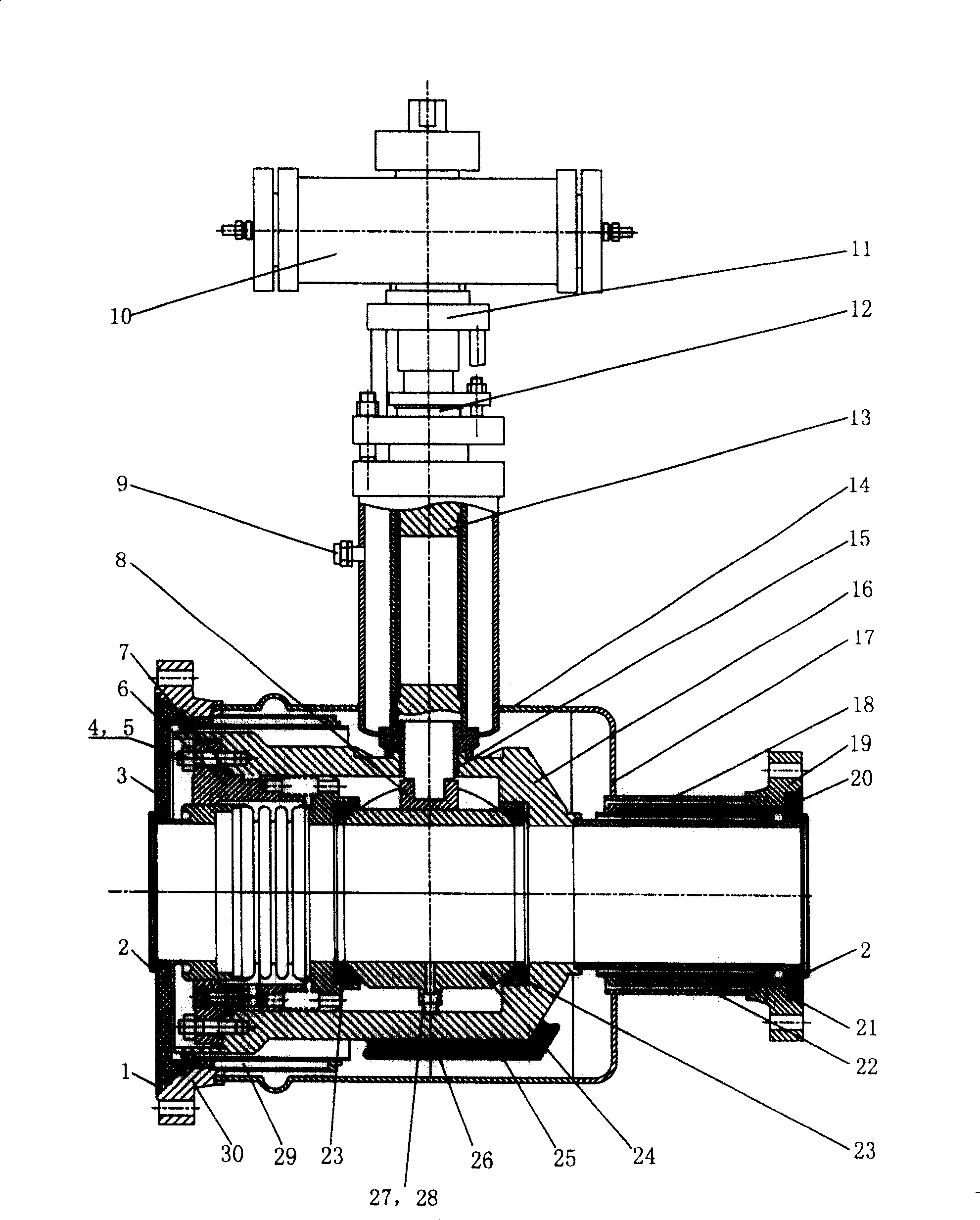
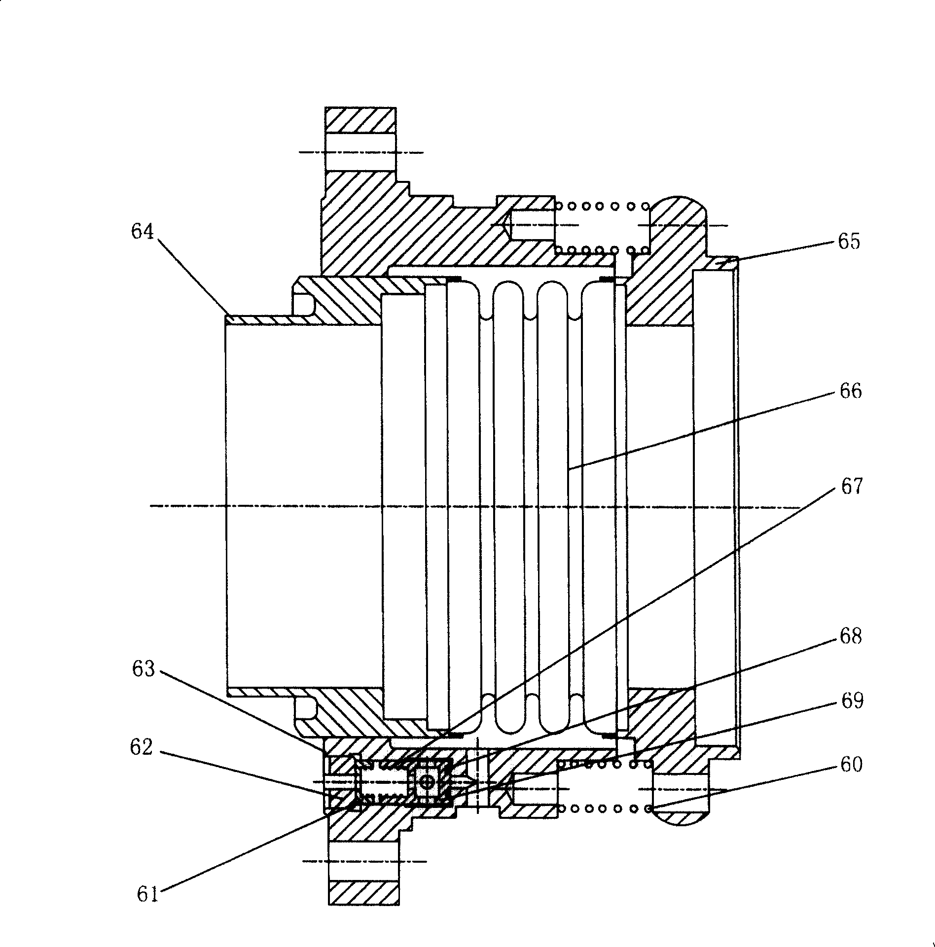
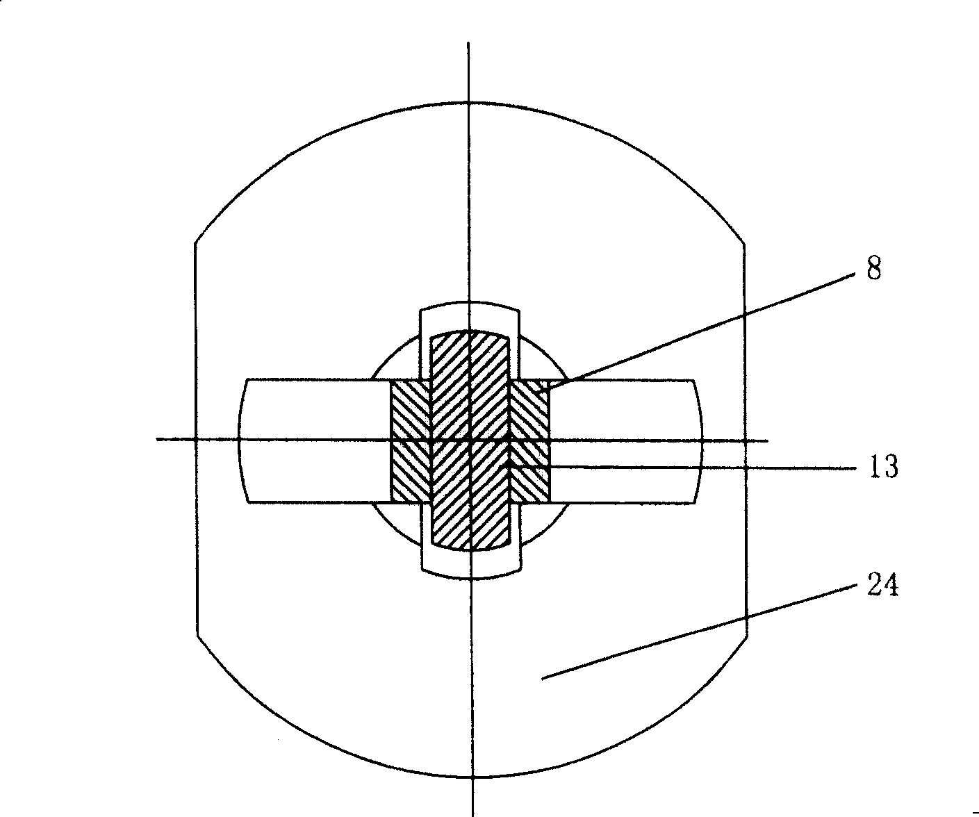
[0029] Such as figure 1 As shown, the structure of a vacuum cryogenic ball valve of the present invention includes a jacket part, a sealing part and a transmission part. The main feature is that the jacket part includes an inlet flange 30 with a thermal bridge, and an outlet flange 19 with a thermal bridge. , between the inlet flange 30 with a thermal bridge and the outlet flange 19 with a thermal bridge, there is a casing 14 and a casing end cover 17; the sealing structure is included in the jacket, and the two ends are fixed on the inlet flange 30 and the valve body 16 on the outlet flange 19, the elastic valve seat 6 fixed on the inlet end of the valve body 16 by studs and nuts 4, 5, and two sealing seats 23 with gaskets embedded on both sides, one of which It is connected with the elastic valve seat 6, and the other part is connected with the valve body 16; the transmission part includes a ball 24 floating in the valve body 16, and the two sides of the ball 24 are respecti...


PUM


Abstract

The vacuum low temperature ball valve comprises the clamping part, seal part and the drive part, with the clamping part composed of inlet flange, outlet flange and the outside shell connected in the middle, the seal structure composed of the valve inside the jacket with both ends fixed on the inlet and outlet flanges, fixed on the spring valve base at the inlet end of the valve through the screw bolt and nut and two seal bases with seal cushion embedded at both sides, with one connected to the spring valve base and the other connected to the valve. The drive part comprises the ball floating inside the valve, both sides of the ball contacting with two seal base, sliders on the top of the ball, with spring base and spring connected to the valve at the bottom of the ball. There are valve bar, guide sleeve and drive mechanism on the slider. It has good seal feature, high reliability, less cold loss, and long working cycle.

Description

technical field [0001] The invention relates to a vacuum cryogenic ball valve used in a cryogenic pipeline delivery system in the technical field of cryogenic engineering. Background technique [0002] The Chinese patent "Taizhou Guanghui Automatic Control Technology Co., Ltd." with the application number of 200510025655.5 discloses a ball valve with a novel sealing structure, which belongs to the field of valve technology. a question. The ball valve with a novel sealing structure includes a valve body, a valve core, a valve stem and a handle. The valve core is located in the valve body, and its center is a through hole. The outer end protrudes from the valve body and is fixedly connected with the handle. The valve stem is movably connected with the valve core. There is a pressure hole in the valve core to make the valve core through hole communicate with the valve stem. A shoulder, and a gasket is provided between the shoulder and the valve body. The sealing structure at...

Claims


Application Information

Patent Timeline
Patent Type & Authority Patents(China)
IPC IPC(8): F16K5/06F16K5/20
Inventor 周亦张景奇刘瑞敏吴光中
Owner 中国航天科技集团公司第一研究院第一〇一研究所
Why Eureka
Try Eureka