Liquid divider

A technology of liquid separator and distribution cavity, which is applied in the direction of refrigeration and liquefaction, fluid circulation arrangement, refrigeration components, etc. It can solve the problems of uneven flow of refrigerant and insufficient heat exchange capacity of evaporator, etc., and achieves compact structure, long length long, noise-reducing effect

Active Publication Date: 2009-04-01
GREE ELECTRIC APPLIANCES INC
View PDF6 Cites 0 Cited by
  • Summary
  • Abstract
  • Description
  • Claims
  • Application Information

AI Technical Summary

Problems solved by technology

[0003] The purpose of the present invention is to provide a liquid separator for an air conditioner, which solves the problem that the refrigerant distribution is uneven and the heat exchange capacity of the evaporator cannot be fully exerted

Method used


Image

  • Liquid divider
  • Liquid divider
  • Liquid divider

Examples


Embodiment 1

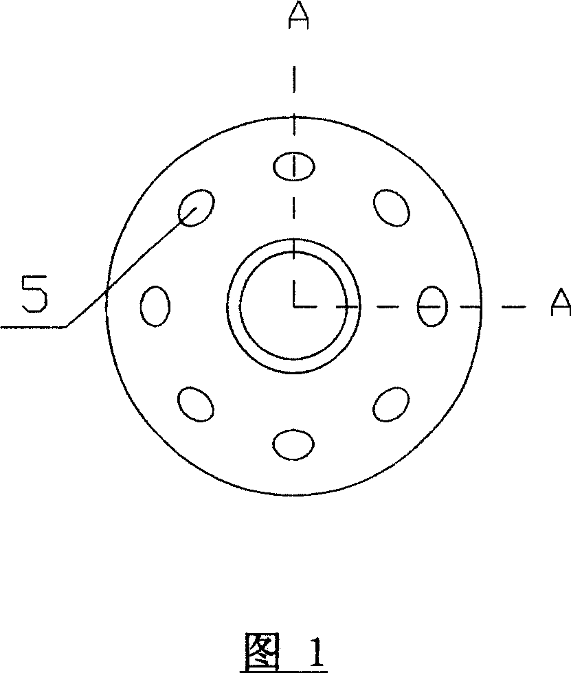
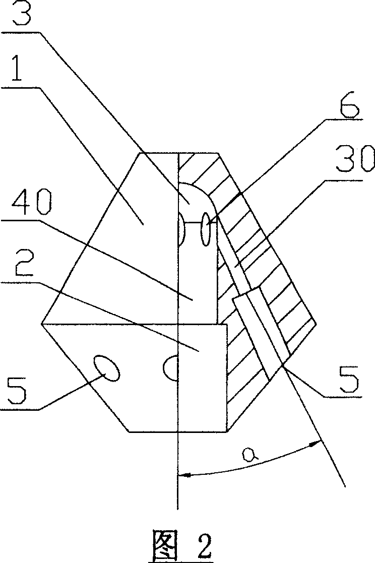
[0020] As shown in Fig. 2, the present invention provides a liquid distributor of an air conditioner, the liquid distributor includes a liquid distributor body 1, a main channel 40 in the liquid distributor body 1 and a liquid outlet chamber 30, and the main channel 40 includes a mixing chamber 2 and a distributing chamber 3. The distributing chamber 3 is branched radially and leads to a plurality of liquid outlet chambers 30. The distribution chamber 3 has a connecting opening 6 communicating with the branched liquid outlet chambers 30. , the angle a between the mixing chamber 2 and the liquid outlet chamber 30 is less than 90 degrees. The main channel 40 is composed of two parts: one part is the mixing chamber 2, and the mixing chamber 2 is composed of two cylindrical cavities with different diameters to form a stepped cylindrical cavity; the other part is the distributing chamber 3, and the The distribution chamber 3 is a part of the inner spherical cavity formed by the upw...

Embodiment 2

[0027] As shown in Figure 3, the biggest difference between this embodiment and Embodiment 1 is:

[0028] In this embodiment, the mixing chamber 2 of the main channel 40 is a cylinder with equal diameters rather than a stepped cylinder composed of two sections of cylinders with unequal diameters.

[0029] As shown in Figure 5 and Figure 7, the spray head 15 is inserted into the main channel 40 of the liquid distributor body 1, and the refrigerant enters the distribution chamber 3 of the liquid dispenser body 1 from the spray hole 16 of the spray head 15, and then passes through the distribution chamber 3 The connection opening 6 communicating with the liquid outlet chamber 30 enters the liquid outlet chamber 30 to achieve the purpose of diverting the refrigerant.


PUM


Abstract

This invention relates to a kind of knockout of air conditioner that belongs to refrigeration field. It settles the problem of refrigerants flow-splitting unevenly, which causes the problem that heat exchanging capacity of evaporator can not fully be given to play. The said distributing cavity draws out many liquid outputting cavities. The said distributing cavity has connecting opening which is communicated with the said branched liquid outputting cavity. The center line included angle a of the said mixed cavity and liquid outputting cavity is less than 90degree. The flow jetting end of knockout uses the design of inner spherical surface. It prevents one-off directly flow-splitting. The inputted and outputted liquids are arranged at the same side of knockout. The liquid inputting straight pipe is long. The flow-splitting is carried out evenly.

Description

technical field [0001] The invention relates to a liquid distributor, in particular to a liquid distributor for an air conditioner. Background technique [0002] In the traditional liquid separator used in the evaporator of the air conditioner, the refrigerant enters and exits in the same direction, which is downstream. In practice, usually due to the limitation of the installation space of the liquid separator, it is difficult to ensure the length of the liquid inlet straight pipe section of the liquid separator, which affects the distribution uniformity of the refrigerant, causing the heat exchange capacity of the evaporator to not be fully utilized, directly reducing The cooling effect of the air conditioner. For the dispenser with spray head, the installation and positioning deviation of the spray head is also one of the common reasons for uneven distribution, and this problem is difficult to control in production. Contents of the invention [0003] The object of the...

Claims


Application Information

Patent Timeline
Patent Type & Authority Patents(China)
IPC IPC(8): F25B41/00
Inventor 张辉马颖江庄嵘梁俊杰
Owner GREE ELECTRIC APPLIANCES INC
Why Eureka
Try Eureka