
Vehicle lamps

A technology for lamps and vehicles, which is applied to lighting devices, fixed lighting devices, light sources, etc., can solve the problems of the up and down direction of the headlights becoming larger, the assembly position is limited, etc., and achieve the effect of increasing the freedom of configuration and reducing the size

Inactive Publication Date: 2009-06-03
STANLEY ELECTRIC CO LTD
View PDF4 Cites 3 Cited by
  • Summary
  • Abstract
  • Description
  • Claims
  • Application Information

AI Technical Summary

Problems solved by technology

[0020] However, this structure makes the overall size of the headlamp vertically larger, so when it is assembled to the front of the car body, the mounting position is also limited.

Method used


Image

  • Vehicle lamps
  • Vehicle lamps
  • Vehicle lamps

Examples


Embodiment 1

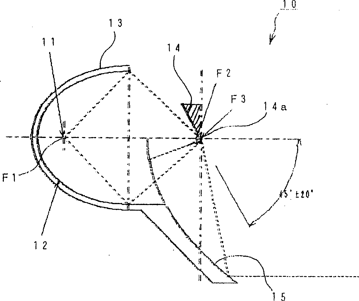
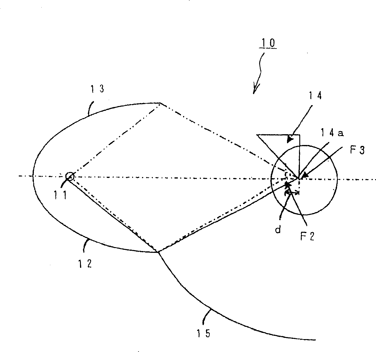
[0049] figure 1 and figure 2 The structure of the first embodiment of the vehicle lamp of the present invention is shown.

[0050] exist figure 1Among them, the vehicle lamp 10 is a headlight of an automobile, and is composed of the following parts: a light bulb 11 as a light source; a first reflective surface 12 and a second reflective surface 13 that reflect light from the light bulb 11 toward the front; The plane reflective surface 14 arranged in the front facing the rear; the third reflective surface 15 that reflects the reflected light from the above-mentioned plane reflective surface 14 toward the front.

[0051] Above-mentioned bulb 11 is the common bulb that the headlamp of automobile or auxiliary headlamp use, for example uses the bulb of discharge lamp such as incandescent lamp, halogen lamp, halogen lamp with infrared reflective film or metal halide lamp, and it is fixed and maintained by lamp holder and be able to supply power to it.

[0052] The above-menti...

Embodiment 2

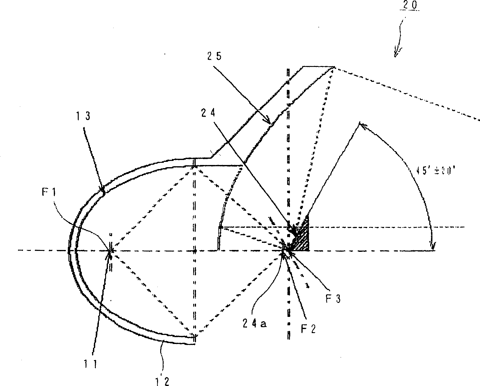
[0068] image 3 and Figure 4 The structure of the second embodiment of the vehicle lamp of the present invention is shown.

[0069] exist image 3 Among them, the local structure of the vehicle lamp 20 is the same as figure 1 The illustrated vehicle lamp 10 is the same, so the same components are given the same reference numerals and their descriptions are omitted.

[0070] The vehicle lamp 20 is a headlight of an automobile, and is composed of the following parts: a light bulb 11 as a light source; a first reflective surface 12 and a second reflective surface 13 that reflect light from the light bulb 11 toward the front; a flat reflective surface 24 disposed toward the rear; and a third reflective surface 25 that reflects light reflected from the flat reflective surface 24 toward the front.

[0071] Above-mentioned planar reflecting surface 24 such as Figure 4 As shown, it is arranged only on the upper side of the optical axis O, and extends obliquely forward from the...


PUM


Abstract

To provide a vehicular lighting fixture which can be constituted small-sized and light-weighted without the occurrence of color separation with a simple configuration. The vehicular lighting fixture 10 is constituted so as to include a recessed first reflecting face 12 facing forward in which a first focus position F1 is positioned in the neighborhood of a light source 11 and in which a second focus position F2 is composed of a composite elliptic face of the lower side from the optical axis arranged on the optical axis O on the front side, a recessed second reflecting face 13 facing forward in which similarly, a second focus position F3 is arranged forwardly than the second focus position F2 and its focus position is composed of the composite elliptic face of the upper side from the optical axis, a recessed third reflecting 15 facing forward in which that focus position is arranged at the second focus position F3 below the first reflecting face and which is composed of a rotational paraboloid, and a flat reflecting face 14 which is extended from the edge line 14a horizontally crossing the second focus position of the second reflecting face toward the upper side and is extended diagonally backward.

Description

technical field [0001] The present invention relates to a lamp for a vehicle used as, for example, a headlight or an auxiliary headlight provided at the front of an automobile. Background technique [0002] In the past, such a headlamp of an automobile is disclosed in Patent Document 1, for example, which has Figure 6 structure shown. [0003] That is, in Figure 6 Among them, the headlight 1 is a spotlight type automobile headlight, which is composed of the following parts: a light bulb 2 as a light source; a reflective surface 3 that reflects light from the light bulb 2 toward the front; a light-condensing projection lens 4; and a light blocking plate 5 arranged in the light path from the bulb 2 to the projection lens 4 for blocking part of the light. [0004] The reflective surface 3 is composed of a compound ellipse, is arranged to have a first focal point F1 near the bulb 2 , and is arranged so that its major axis is along the optical axis of the bulb 2 . [0005] He...

Claims


Application Information

Patent Timeline
Patent Type & Authority Patents(China)
IPC IPC(8): F21S8/10F21V7/00F21V7/10F21V13/00F21V11/00F21W101/10F21Y101/00
CPCF21S41/321F21S41/365
Inventor 山本勉
Owner STANLEY ELECTRIC CO LTD
Learn More