

Manipulating device
A technology of operating device and rotating operation, which is applied in the direction of mechanical control devices, instruments, calculations, etc., can solve the problem of low operator convenience and achieve the effect of easy operation
- Summary
- Abstract
- Description
- Claims
- Application Information
AI Technical Summary
Problems solved by technology
Method used
Image

Examples
no. 1 Embodiment approach
[0072] [structure]
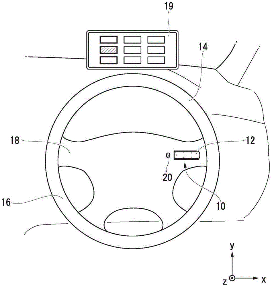
[0073] Next, an embodiment of the operating device 10 of the present invention will be described with reference to the drawings. figure 1 It is a figure which shows an example when the operation device 10 which concerns on 1st Embodiment is arrange|positioned. Such as figure 1 As shown, the switch portion 12 of the operating device 10 is arranged on the spoke portion 18 of the rim portion 16 supporting the steering wheel 14 . The spoke portions 18 support the circular rim portion 16 and are T-shaped when the steering wheel 14 is in the forward position (ie, the position the steering wheel 14 is in when it is turned). An activation switch 20 for activating a display unit 19 for displaying information for inputting commands is disposed on a side portion of the switch unit 12 .
[0074] The switch part 12 is disposed in the spoke part 18, and is substantially in the horizontal direction ( figure 1 left and right direction) on the part of the support rim p...
no. 2 Embodiment approach
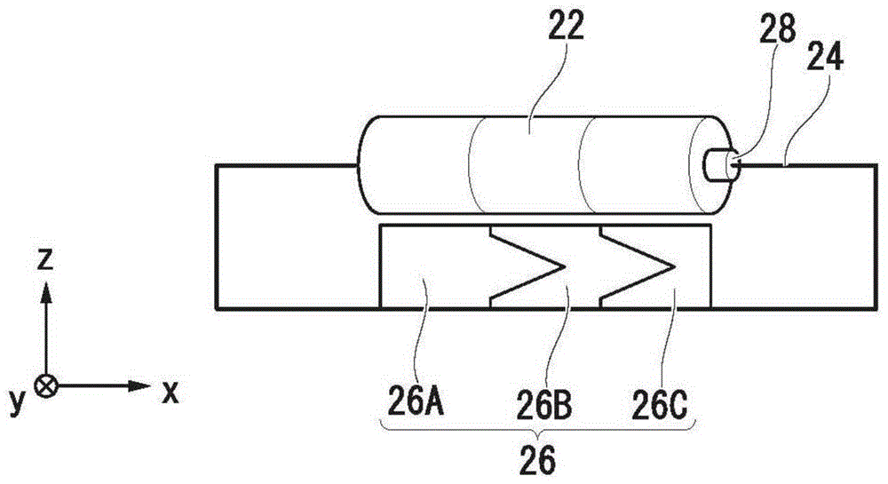
[0123] Below, refer to Figure 11 The operation device 10 according to the second embodiment will be described. Figure 11 It is a figure which shows an example of the internal structure of the operation device 10 which concerns on 2nd Embodiment. Figure 11 The illustrated operation device 10 has a click feeling generating pin 70 in addition to the configuration illustrated in the first embodiment. The click feeling generating pin 70 is arranged on the opposite side (inside the switch unit 12 ) to the side of the rotating member 22 where the command issuing body approaches or contacts, and is arranged facing the rotating member 22 . On the outer edge of the rotating member 22, bridging portions are provided at predetermined intervals, and the click feeling generating pin 70 abuts against the bridging portions with a predetermined biasing force. The click feeling generating pin 70 abuts with a predetermined urging force on bridging portions (concavo-convex portions, not show...
no. 3 Embodiment approach
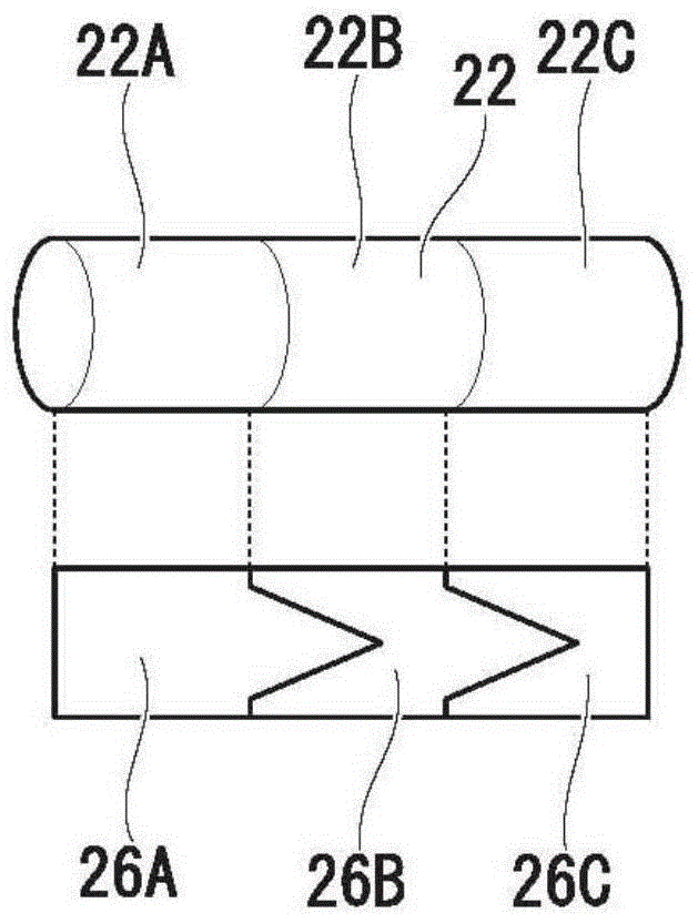
[0127] Below, refer to Figure 12 , the operation device 10 to which this embodiment according to the third embodiment is applied will be described. Figure 12 It shows an example of the internal structure of the operating device 10 . Unlike the first embodiment, in Figure 12 In the shown operating device 10, three rotating parts 22 ( Figure 12 , 22a, 22b, 22c). In addition, in the first embodiment, the position detection sensor 26 provided separately from the rotating member 22 outputs a signal corresponding to the position of the command issuing body; The member 22 incorporates a mechanism for outputting information corresponding to the position of the command issuing body facing the rotating member 22 .
[0128] In the operation device 10 of the third embodiment described above, for example, the rotating members 22 a , 22 b , and 22 c are position detection sensors 26 as shown in the figure. When the command issuing body approaches or touches the position correspondi...
PUM
 Abstract
Description
Claims
Application Information