
Caliper for measuring distance between roller and object and distance measuring method

A technology of objects and fixtures, applied in the direction of measuring devices, mechanical devices, mechanical measuring devices, etc., can solve problems such as inconvenient and poor precision

Inactive Publication Date: 2009-06-10
NIPPON PETROCHEMICAL CO LTD
View PDF4 Cites 0 Cited by
  • Summary
  • Abstract
  • Description
  • Claims
  • Application Information

AI Technical Summary

Problems solved by technology

There is a method of using a tape measure on site, but its accuracy is poor, and the tape measure must be wound on a roll, which is inconvenient

Method used


Image

  • Caliper for measuring distance between roller and object and distance measuring method
  • Caliper for measuring distance between roller and object and distance measuring method

Examples


Embodiment Construction

[0013] Embodiment of the invention

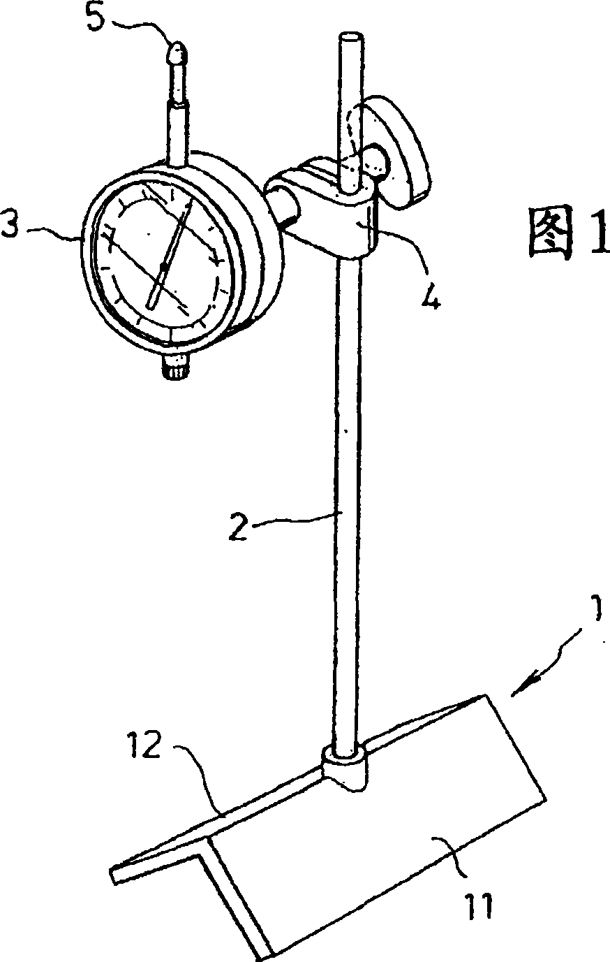
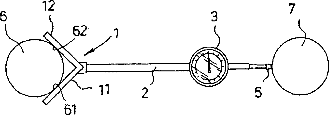
[0014] Hereinafter, examples of embodiments of the present invention will be described based on the drawings. FIG. 1 is a schematic perspective view of an example of a jig for measuring the distance between a roller and an object. In Fig. 1, 1 is a support body, 2 is a rod-shaped body extending from the support body to the other roller, and 3 is a micro-displacement gauge fixed with a clamp 4 or the like at the front end of the rod-shaped body (as an example, shown is Dial indicator), 5 is the measurement end of the micro-displacement gauge (as an example of the dial indicator). figure 2 It is a schematic diagram showing an example of the method for measuring the distance between a roller and an object according to the present invention. exist figure 2 Among them, 1 is a support body, 2 is a rod-shaped body extending from the support body to the other object (roller, etc.), and 3 is a micro-displacement gauge fixed to the front end of th...


PUM


Abstract

Provided is a jig for measuring distance between a roll and other object and a measuring method for accurately centering roll group used in manufacturing and processing film and the like. The roll distance measuring method is characterized by measuring distance between the roll and the object by that the inner surface of the jig for measuring distance between the roll and the object having a support (1) having two contact surfaces contacting with two lines on the roll surface in parallel to the axis of one roll, a rod-like body (2) extended from the support toward the other object (for example, a roll) and a micro-displacement gauge (for example, a dial gauge) (3). and the support of the jig and one roll surface contact with two lines and that the measuring end of the micro-displacement gauge contact the surface of the other object (for example, the roll).

Description

technical field [0001] The present invention relates to a jig for measuring the distance between a roll and an object such as another roll used in the manufacture and processing of the strip-shaped film of the present invention, and a method for measuring the distance between a roll and an object using the jig. Background technique [0002] Rolls are indispensable elements in the production of strip-shaped polymer films, coating other materials on the film surface, laminating films, surface processing, and stretching. Generally, a plurality of rolls are used in combination, but if the rolls are not parallel, there will be problems such as uneven film thickness, wrinkles, uneven coating thickness, and uneven stretching. Especially in films that require uniformity such as optical elements, these problems caused by the non-parallel rolls will have a great impact on the quality of the product, so the distance between the rolls must be closely adjusted, that is, the centering of ...

Claims


Application Information

Patent Timeline
Patent Type & Authority Patents(China)
IPC IPC(8): G01B5/14G01B5/00G01B5/25
Inventor 清原稔和坂田敏宽福田靖
Owner NIPPON PETROCHEMICAL CO LTD
Learn More