Microwave oven

A technology of microwave ovens and plates, which is applied in the field of microwave ovens, can solve problems such as collisions and complicated food cooking, and achieve the effect of preventing collisions

Inactive Publication Date: 2009-07-15
LG ELECTRONICS (TIANJIN) APPLIANCES CO LTD
View PDF3 Cites 0 Cited by
  • Summary
  • Abstract
  • Description
  • Claims
  • Application Information

AI Technical Summary

Problems solved by technology

Since two operations are performed, that is, the operation of rotating the heater 19 and the operation of putting in the plate 21, there is a disadvantage that the rotating heater 19 is complicated when cooking food.
[0014] In addition, if the moving speed of the dish 21 in the cooking chamber 11 is relatively faster than the rotating speed of the rotating heater 19, a phenomenon that they collide with each other occurs.

Method used


Image

  • Microwave oven
  • Microwave oven
  • Microwave oven

Examples


Embodiment Construction

[0065] A preferred embodiment of the microwave oven according to the present invention will be described in detail below with reference to the accompanying drawings.

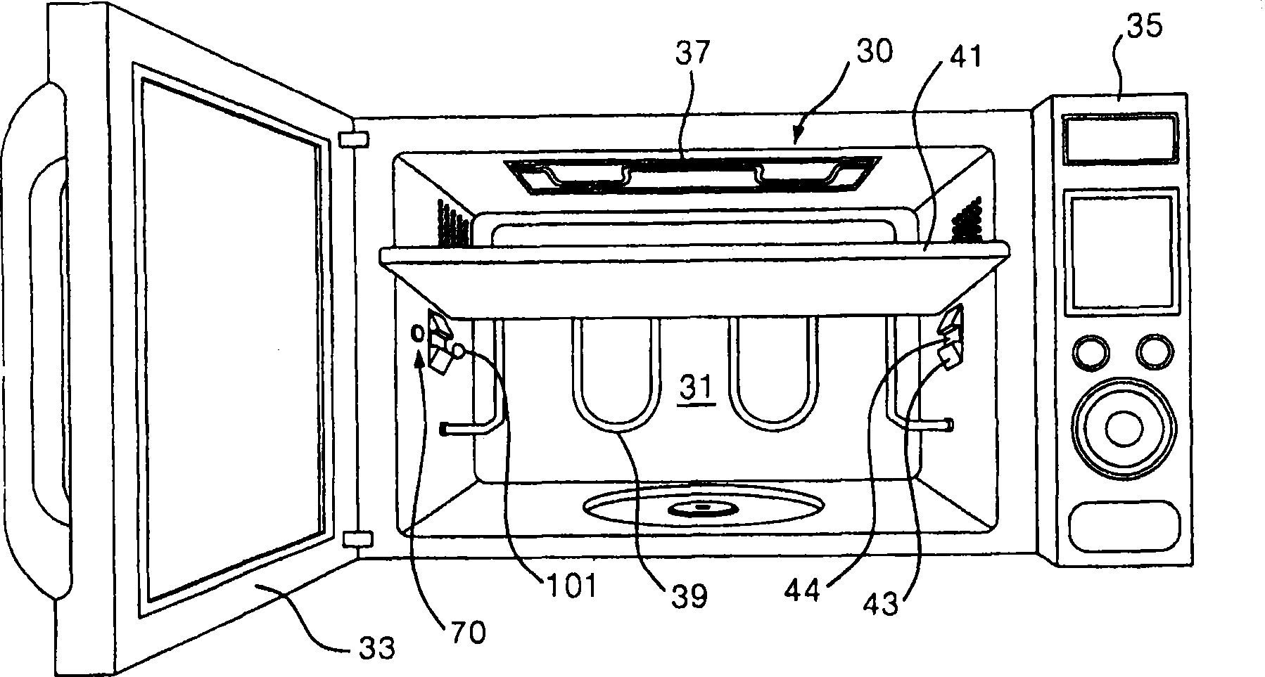
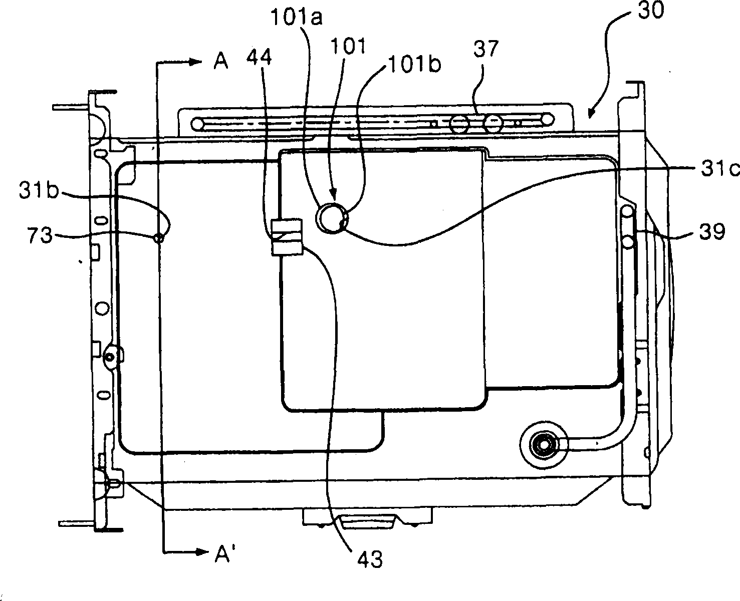
[0066] figure 2 Illustrating a preferred embodiment of a microwave oven according to the present invention, image 3 The illustration is viewed from inside the cooking compartment figure 2 In the side of the embodiment, Figure 4 icon image 3 A-A line profile in, Figure 5 and Figure 6 icon figure 2 An important part of the embodiment.

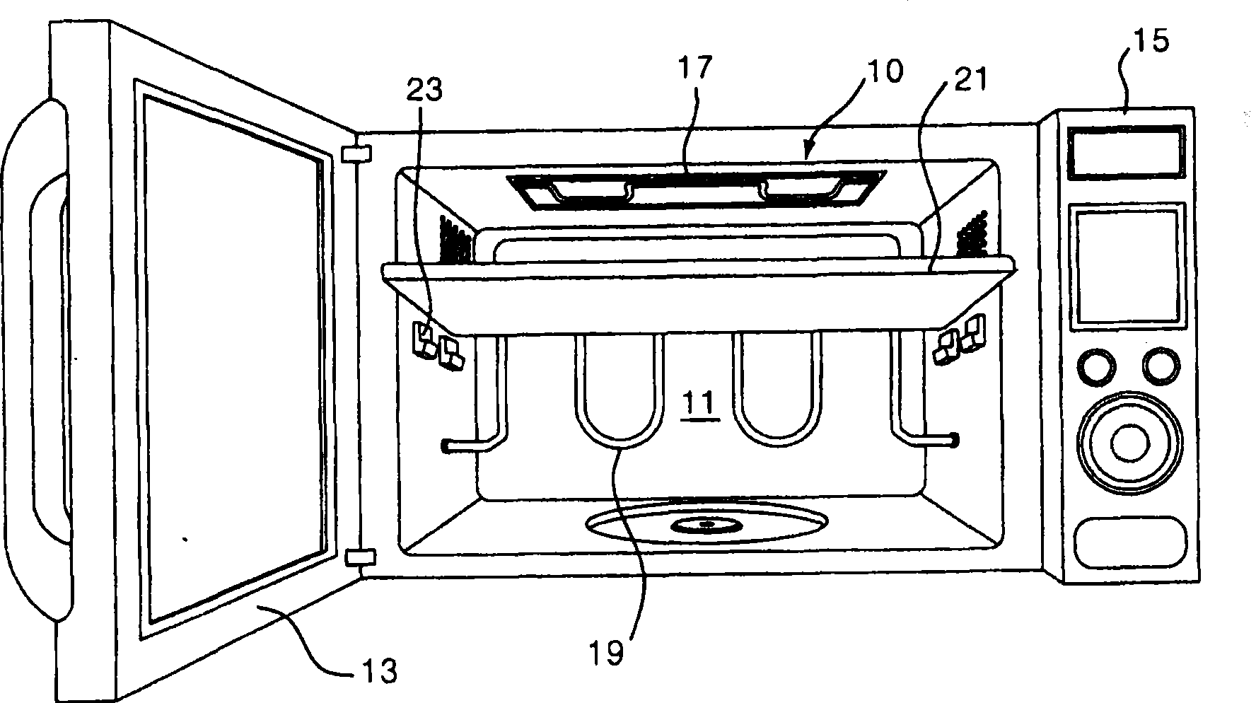
[0067] As shown in the figure, the cavity assembly 30 of the microwave oven is equipped with a cooking chamber 31 for cooking food. Furthermore, in order to selectively open and close the cooking chamber 31 , a door 33 is rotatably attached to one side of the cooking chamber 31 .

[0068] Inside the cavity assembly 30 corresponding to the other side of the cooking chamber 31, there is a storage room (not shown) for installing various electronic components. In addit...


PUM


Abstract

The present invention relates to a microwave oven. It is characterized by that a turning hole is formed on one side of microwave oven cooking chamber, a plug-in guide portion is matched with said through turning hole, selectively positioned on the tray moving pathway and can be driven by a drive motor to make forward rotation or backward rotation. Said drive motor is controlled by a change-over switch, including first stopping switch and second stopping switch which can be alternatively operated. According to said invention the upper surface and undersurface of food to be cooked can be simultaneously heated by heater.

Description

technical field [0001] The present invention relates to a microwave oven, and more particularly, to a microwave oven in which a heater is rotatably installed at the rear end of a cooking chamber. Background technique [0002] figure 1 A microwave oven according to the prior art is shown. [0003] As shown in the figure, a cooking chamber 11 for placing food is formed inside the cavity assembly 10 of the microwave oven. The cooking chamber 11 is selectively opened and closed by a door 13 that is installed on the oven chamber assembly 10 and rotates toward the front of the microwave oven. [0004] In addition, a cabinet (not shown) for installing various electronic components such as a magnetron and a high-voltage transformer is provided on one side of the cavity assembly 10 . A control unit 15 is provided on the front of the oven cavity assembly 10 corresponding to the front of the electric storage room to input various operation signals of the microwave oven and display v...

Claims


Application Information

Patent Timeline
Patent Type & Authority Patents(China)
IPC IPC(8): F24C7/02F24C7/06
Inventor 余泰洪
Owner LG ELECTRONICS (TIANJIN) APPLIANCES CO LTD
Why Eureka
Try Eureka