
Device for measuring optical fiber Raman gain coefficienct
A Raman gain coefficient and optical fiber measurement technology, which is applied in the field of optical communication devices, can solve problems affecting gR accuracy, limited measurement range, and complicated testing process, and achieve the effects of no polarization dependence, wide range, and good stability
- Summary
- Abstract
- Description
- Claims
- Application Information
AI Technical Summary
Problems solved by technology
Method used
Image

Examples
Embodiment Construction
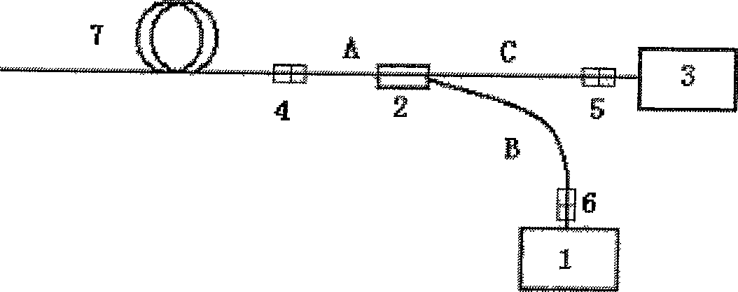
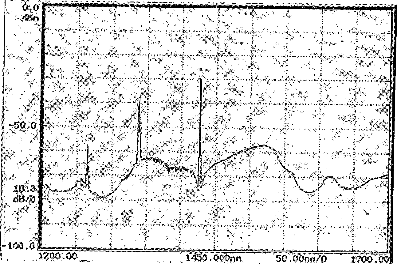
[0015] refer to figure 1 The device for measuring fiber Raman gain coefficient of the present invention comprises a fiber laser 1, a pump-signal fiber wavelength division multiplexer 2 and a fiber optic spectrometer 3, and the input terminal A of the pump-signal fiber wavelength division multiplexer 2 is connected to a useful In the first optical fiber joint 4 connected to the single-mode optical fiber 7 to be tested, the output end C of the pump-signal optical fiber wavelength division multiplexer 2 is connected to the optical fiber spectrometer 3 through the second optical fiber joint 5, and the pump-signal optical fiber wavelength division The pumping end B of the multiplexer 2 is connected to the fiber laser 1 through the third fiber connector 6 .
[0016] In the example, the measured single-mode fiber 7 connected to the first fiber optic connector 4 is a 5km DCF fiber, the pump-signal fiber wavelength division multiplexer 2 uses a 1X2 coupler, the fiber optic spectrometer...
PUM
 Abstract
Description
Claims
Application Information