Clutch having transport fixed device, and method for producing clutch

A clutch and transmission technology, applied in the field of clutches, to achieve the effect of improving economic efficiency, time efficiency and high flexibility

Active Publication Date: 2018-01-12
SCHAEFFLER TECH AG & CO KG
View PDF17 Cites 0 Cited by
  • Summary
  • Abstract
  • Description
  • Claims
  • Application Information

AI Technical Summary

Problems solved by technology

[0007] In other words, the clutches known from the prior art therefore have the disadvantage that at least one additional work step is required for the transport fastening, such as cutting and remachining of the individual components, which results in additional costs

Method used


Image

  • Clutch having transport fixed device, and method for producing clutch
  • Clutch having transport fixed device, and method for producing clutch
  • Clutch having transport fixed device, and method for producing clutch

Examples


Embodiment Construction

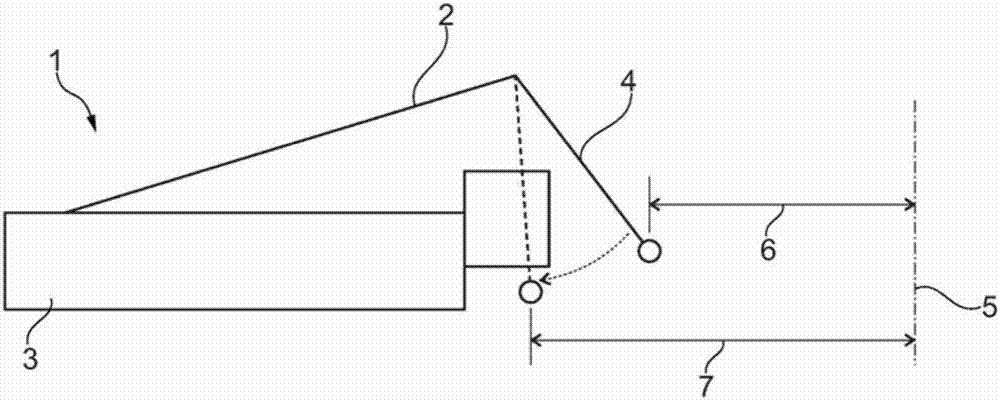
[0036] figure 1 A schematic diagram of clutch 1 is shown. In an operating state, the pressure pot 2 can be coupled to the pressure plate 3 so that a torque can be transmitted via the clutch 1 . Furthermore, a clamping plate 4 is provided on the pressure pot 2 in order to achieve an axial fixation, preferably during transport of the clutch 1 . figure 1 The arrangement of is arranged rotationally symmetrically around the axis of rotation 5 . The axial direction is arranged on the axis of rotation 5 .

[0037] The clamping plate 4 is designed such that it is not axially coupled / connected to the compression plate 3 in the first operating state. This first operating state is shown by means of a solid line. In the second operating state, the clamping plate 4 assumes such a position that the pressure vessel 2 and the pressure plate 3 are at least partially coupled axially figure 1 Indicated by dashed lines.

[0038] The plastic deformation according to the invention of the clam...


PUM


Abstract

The invention relates to a clutch (1) of a power transmission system. The clutch comprises at least one pressure tank (2), which can be operated by a pressing plate (3) to realize the torque transmission between the component fixed to a motor and a component fixed to a transmission. The pressure tank (2) has a deformable clamping plate (4), which is configured to generate coupling between the pressure tank (2) and the pressing plate (3). The invention also relates to a method for producing clutch.

Description

technical field [0001] The invention relates to a clutch for use in a drive train of a motor vehicle, said clutch having at least one pressure pot which can be actuated such that it is now fastened to the engine via a pressure plate Torque transmission between components on the transmission, such as a dual mass flywheel, and components fixed on the transmission, such as the first transmission input shaft. [0002] Furthermore, the invention relates to a method for producing and / or installing a clutch. Background technique [0003] Such a clutch is known from German patent application DE 10 2011 104 247 A1. It discloses a dual clutch arrangement by means of which in a motor vehicle an engine-side input shaft can be coupled with two transmission-side output shafts arranged coaxially with one another substantially without interruption of the tractive force. In this case, the dual clutch arrangement is designed in a space-optimized manner via the receiving recess. Since the l...

Claims


Application Information

Patent Timeline
Patent Type & Authority Applications(China)
IPC IPC(8): F16D13/60F16D13/71
CPCF16D13/585F16D13/70
Inventor 亚历山大·康斯坦丁诺夫
Owner SCHAEFFLER TECH AG & CO KG
Why Eureka
Try Eureka