Method for eliminating particles contained in exhaust gases, fibrous layer and particulate filter

A particle filter, fiber layer technology, applied in the field of fiber layer, to achieve the effect of simplifying manufacturing

Active Publication Date: 2009-09-02
EMITEC EMISSIONSTECHNIK +1
View PDF10 Cites 2 Cited by
  • Summary
  • Abstract
  • Description
  • Claims
  • Application Information

AI Technical Summary

Problems solved by technology

Particularly outstanding are the low pressure losses and the possibility of such a filter system being installed relatively close to the internal combustion engine - where particle traps are often subjected to higher temperatures

Method used


Image

  • Method for eliminating particles contained in exhaust gases, fibrous layer and particulate filter
  • Method for eliminating particles contained in exhaust gases, fibrous layer and particulate filter
  • Method for eliminating particles contained in exhaust gases, fibrous layer and particulate filter

Examples


Embodiment Construction

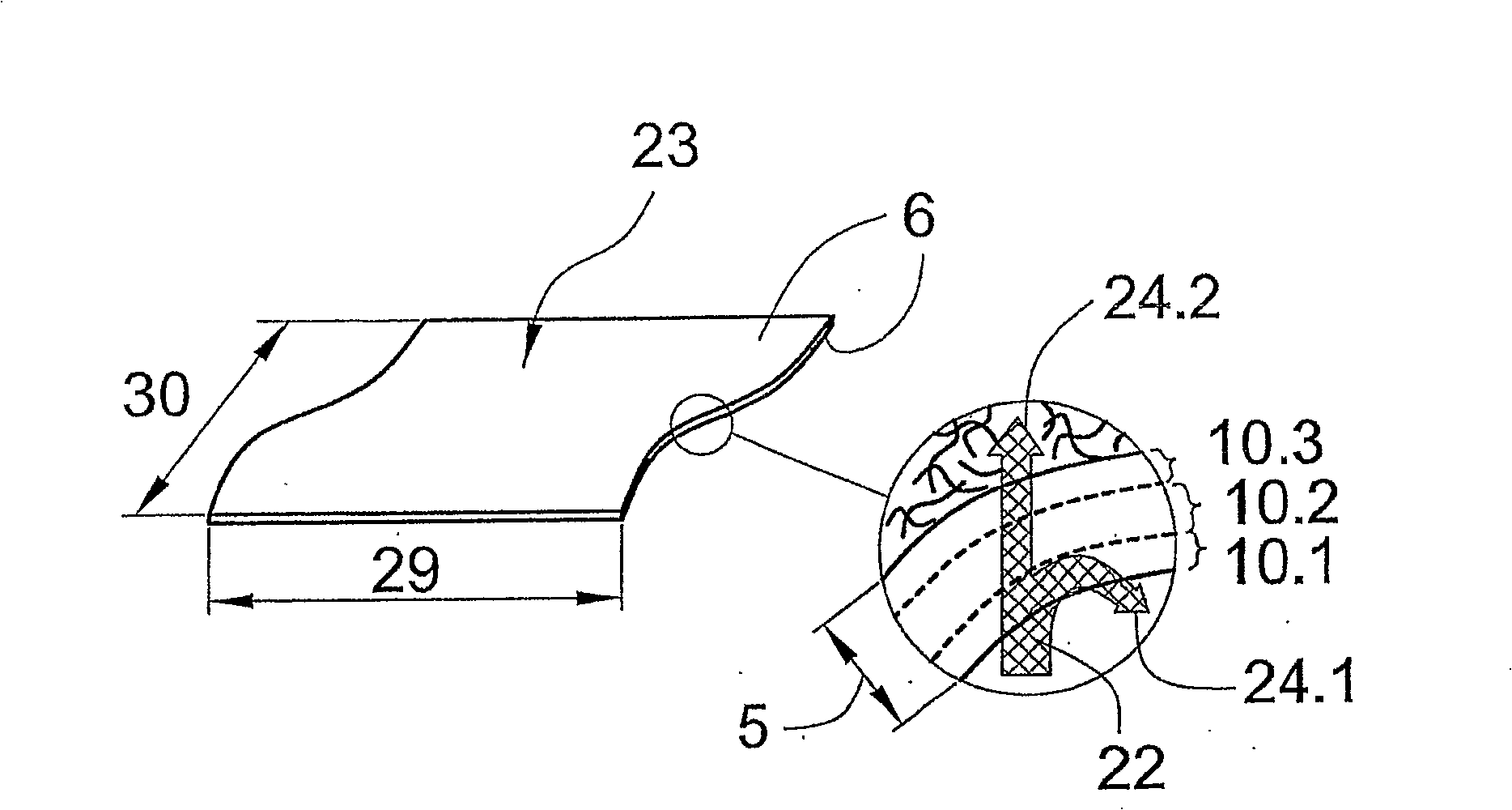
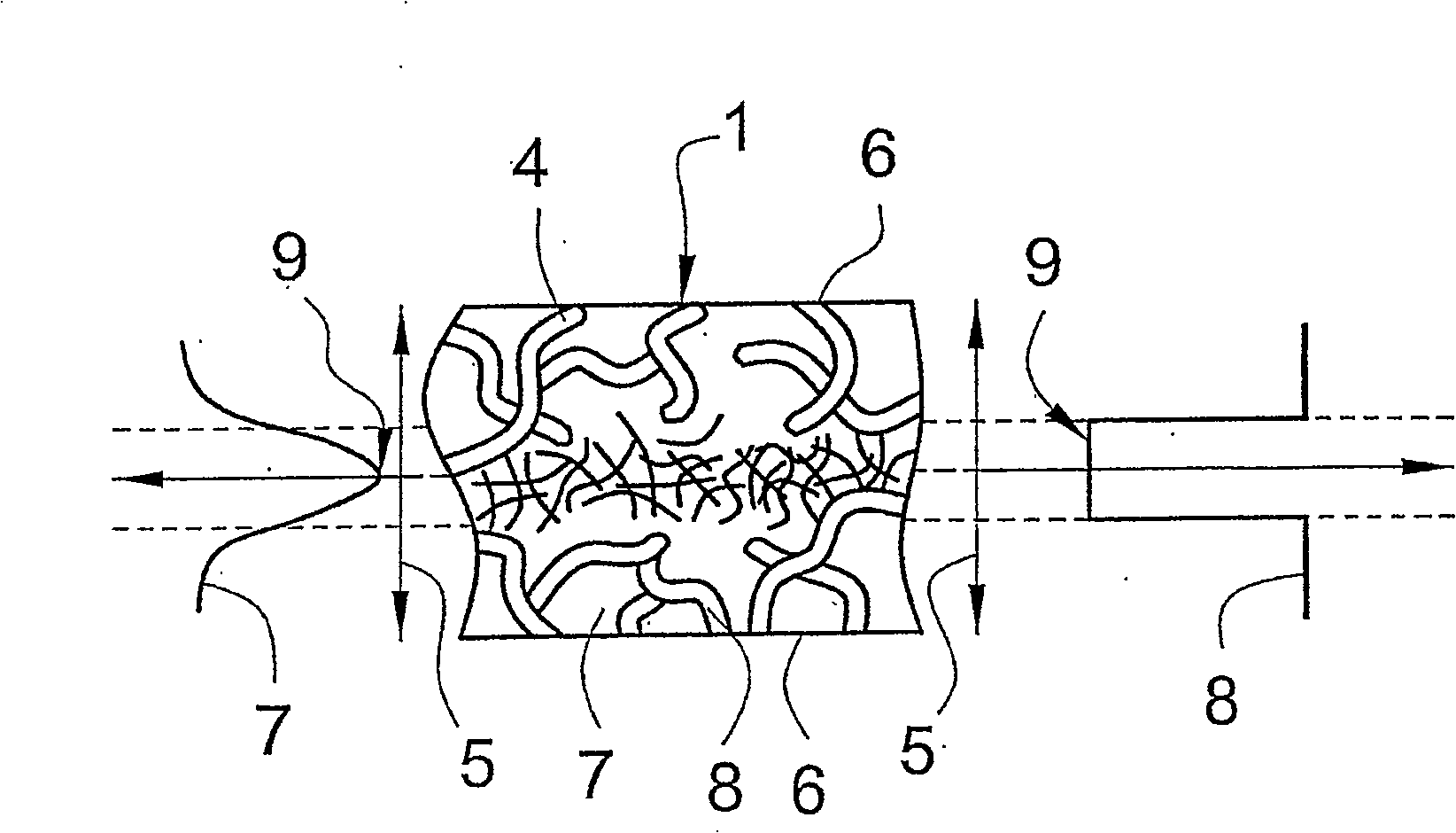
[0044] figure 1 A filter layer 23 is shown in a schematic perspective view, which is usually produced with a defined layer length 29 and layer width 30 . The filter layer 23 (or fibrous layer 1 ) is bounded by two faces 6 which ultimately define the layer thickness 5 of the filter layer 23 . In the direction of the layer thickness 5 , the air-permeable filter layer 23 has a plurality of subregions 10 ( 10 . 1 , 10 . 2 , 10 . 3 ), which differ with respect to the parameters describing the filter layer 23 . If the filter layer 23 is designed as a fiber layer 1 , characteristic parameters of the filter layer 23 include, for example, the porosity 7 or the diameter 8 of the fibers 4 .

[0045]As can be seen from the partial view, the air flow 22 emerging on the filter layer 23 is partially squeezed into the inner region of the filter layer 23 . After the entire air flow 22 has flowed through the first subregion 10.1, it reaches the second subregion 10.2. The second subregion 10 ...


PUM


Abstract

The invention relates to a method for removing particles (21) from an air flow (22) by means of an air-permeable filter layer (23) having subregions (10) with different size parameters in the layer thickness (5) direction. The parameters relate at least to the porosity (7) of the filter layer (23), the fiber diameter (8) of the fibers (4) or the fiber type composition. The method is characterized in that the gas flow (22) is divided into component gas flows (24), which flow through different subregions (10) of the fiber layer (23). The invention also relates to a fiber layer, a particle filter, an exhaust system and a vehicle based on the method.

Description

technical field [0001] The invention relates to a fibrous layer suitable for use in exhaust equipment for mobile internal combustion engines. Furthermore, a particle filter for the same purpose is proposed, and the invention furthermore relates to a method for removing particles from the exhaust gas of an internal combustion engine with a breathable filter layer. Background technique [0002] In order to reduce the emission of particles in the exhaust gases produced by combustion processes, it is known to use particle traps made of ceramic matrices. These traps have channels so that the exhaust gas to be cleaned can flow into the particle traps. The ends of adjacent channels are alternately closed so that exhaust gas enters the channel at the inlet end, is forced through the ceramic wall, and is re-exited at the outlet end along the adjacent channel. Such filters achieve an efficiency of about 95% over the entire range of particle sizes that occur. [0003] In addition to...

Claims


Application Information

Patent Timeline
Patent Type & Authority Patents(China)
IPC IPC(8): F01N3/022B01D39/20D04H1/4234
CPCB01D39/2027F01N3/0226Y02T10/20Y10S55/30Y02T10/12F01N3/022B01D39/20
Inventor P·希尔特R·布吕科T·黑里希
Owner EMITEC EMISSIONSTECHNIK
Why Eureka
Try Eureka