Calculation method, system, device and storage medium of filter parameters

A calculation method and filter technology, applied in the field of filters, can solve the problems of increased conduction electromagnetic interference, filter failure, and failure to consider the influence of passive filter insertion loss, etc., to achieve the effect of preventing failure and improving effectiveness

Active Publication Date: 2022-05-27
SHENZHEN UNIV
View PDF3 Cites 0 Cited by
  • Summary
  • Abstract
  • Description
  • Claims
  • Application Information

AI Technical Summary

Problems solved by technology

Although the efficiency of the system is improved to a certain extent, it also leads to a sharp increase in the conducted electromagnetic interference in the system, which cannot be ignored. It can be effectively suppressed by designing an electromagnetic interference filter
However, there is still no relatively complete theoretical basis for the design of passive electromagnetic interference filters. Generally, the design is based on a certain experience, and the nonlinear characteristics of the system impedance are basically ignored. Even if this is recognized, it is not very good. way to solve
The design of the conducted electromagnetic interference filter in the grid-connected inverter is based on the limit value of the corresponding standard and the actual measurement value of the system to obtain the proper insertion loss, and does not take into account the nonlinear impedance of the noise source on the passive filter. effect of tor insertion loss
[0003] The traditional electromagnetic interference filter is ideally designed based on the demand value of the insertion loss obtained by measurement and comparison. The filter fails due to the impedance change caused by the nonlinear device in the system during operation, and the electromagnetic The effectiveness of the parameters of the interference filter is low

Method used


Image

  • Calculation method, system, device and storage medium of filter parameters
  • Calculation method, system, device and storage medium of filter parameters
  • Calculation method, system, device and storage medium of filter parameters

Examples


Embodiment Construction

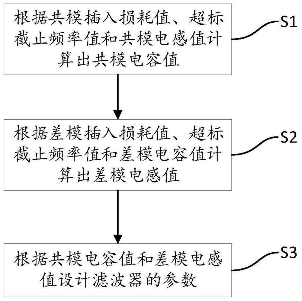
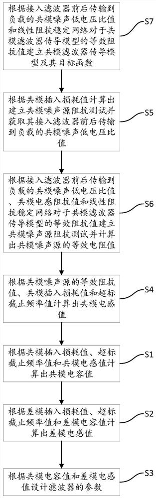
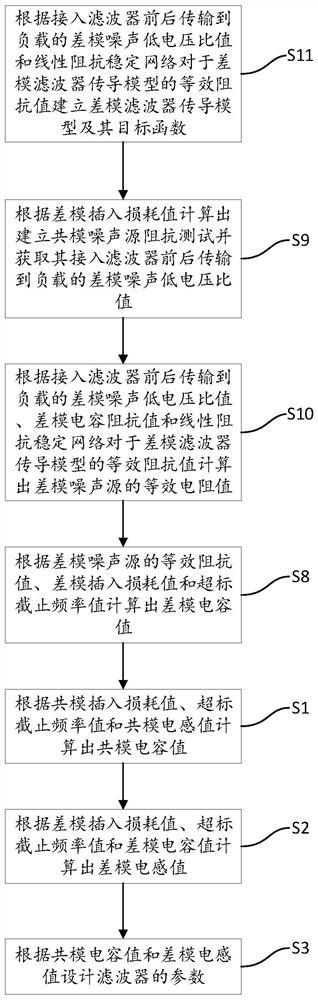
[0045] The technical solutions in the embodiments of the present invention will be clearly and completely described below with reference to the accompanying drawings in the embodiments of the present invention. Obviously, the described embodiments are only a part of the embodiments of the present invention, but not all of the embodiments. Based on the embodiments of the present invention, all other embodiments obtained by those of ordinary skill in the art without creative efforts shall fall within the protection scope of the present invention.

[0046] It should be noted that the technical solutions between the various embodiments can be combined with each other, but must be based on the realization by those of ordinary skill in the art. When the combination of technical solutions is contradictory or cannot be realized, it should be considered that the combination of such technical solutions does not exists, and it is not within the protection scope of the present invention. ...


PUM


Abstract

The present invention discloses a calculation method, system, equipment and storage medium for the parameters of a filter, comprising the steps of: according to the value of the common-mode insertion loss exceeding the standard cut-off frequency value f * and common mode inductance value L CM Calculate the common mode capacitor value C CM ;According to the differential mode insertion loss value exceeding the cut-off frequency value f * and differential mode capacitance C DM Calculate the differential mode inductance value L DM ; According to the common mode capacitance C CM and differential mode inductance L DM Design the parameters of the filter. The calculation method, system, equipment and storage medium of the parameters of the filter of the present invention obtain the common-mode capacitance value and the differential-mode inductance value through calculation respectively, thereby designing the parameters of the filter according to the common-mode capacitance value and the differential-mode inductance value, and improving The effectiveness of the parameters of the filter prevents the filter from failing due to impedance changes caused by nonlinear devices in the system during operation.

Description

technical field [0001] The present invention relates to the field of filters, in particular to a method, system, device and storage medium for calculating parameters of a filter. Background technique [0002] With the continuous development of semiconductor materials, the switching frequency of power switch tubes used in power electronic systems is getting higher and higher. Although the efficiency of the system is improved to a certain extent, it also leads to a sharp increase in the conducted electromagnetic interference in the system, which cannot be ignored. It can be effectively suppressed by designing an electromagnetic interference filter. However, there is still no perfect theoretical basis for the design of passive electromagnetic interference filters. Generally, the design is carried out on the basis of certain experience, and the nonlinear characteristics of the system impedance are basically ignored. Even if it is recognized, it is not very good method to solve....

Claims


Application Information

Patent Timeline
Patent Type & Authority Patents(China)
IPC IPC(8): G06F30/367
CPCG06F30/39
Inventor 刘艺涛江师齐王怀智王贵斌彭建春
Owner SHENZHEN UNIV
Why Eureka
Try Eureka