Emergency braking device for a lift cabin

A technology for emergency braking, elevator cars, used in transportation and packaging, elevators, etc.

Active Publication Date: 2009-12-23
WITTUR
View PDF8 Cites 0 Cited by
  • Summary
  • Abstract
  • Description
  • Claims
  • Application Information

AI Technical Summary

Problems solved by technology

This solution takes into account the situation, dictated by vibrations, tolerances, etc., that one of the two wheels does not make good contact with the guide rail for a while, and therefore does not roll at a speed that effectively represents the speed of the elevator car

Method used


Image

  • Emergency braking device for a lift cabin
  • Emergency braking device for a lift cabin
  • Emergency braking device for a lift cabin

Examples


Embodiment Construction

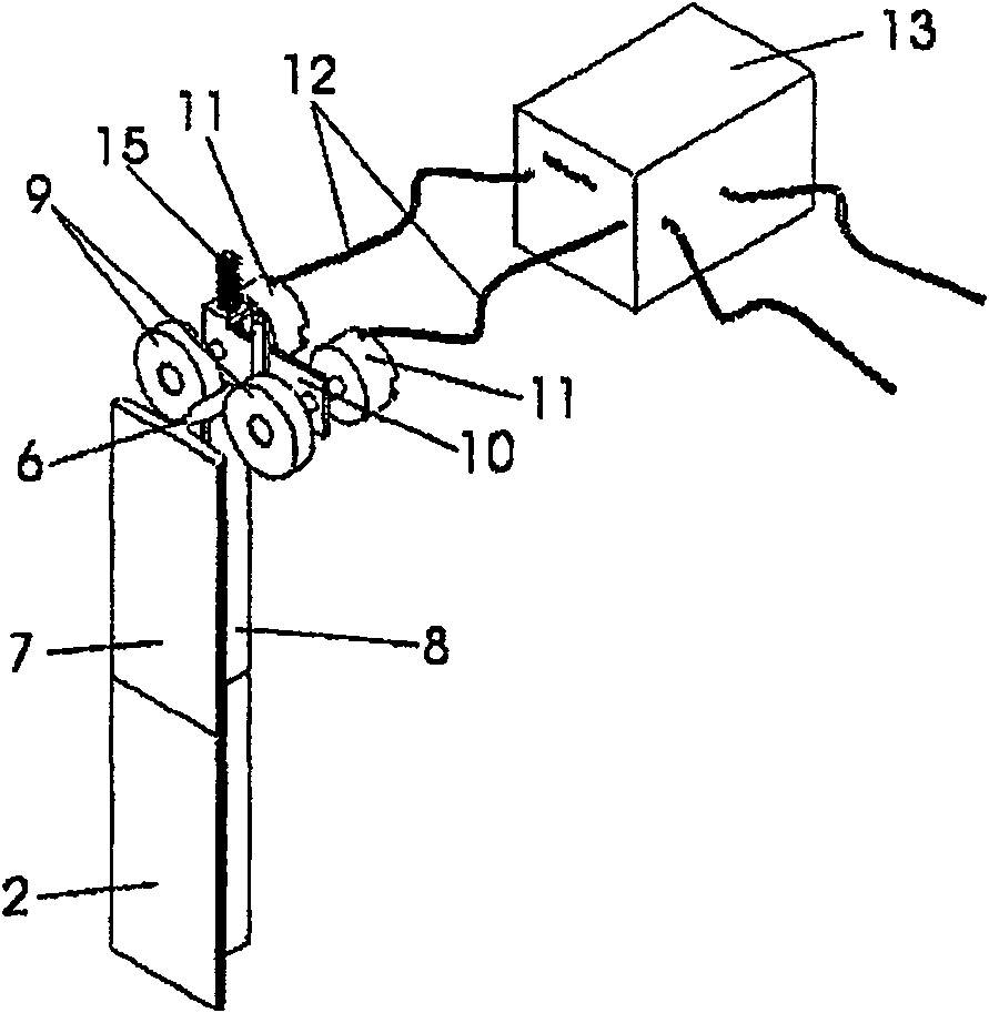
[0029] Such as figure 1 As shown, the guide rail 2 has a rail head 8 connected via a web 6 to a rail base 7 .

[0030] The wheels 9 rest against the sides of the rail head 8 and are held rotatably in the rocker 10 (see also figure 2 ) and is connected to the sensor 11 in a rotationally fixed manner. The sensor 11 is connected via a signal line 12 to a mechanism 13 for detecting excessive speed.

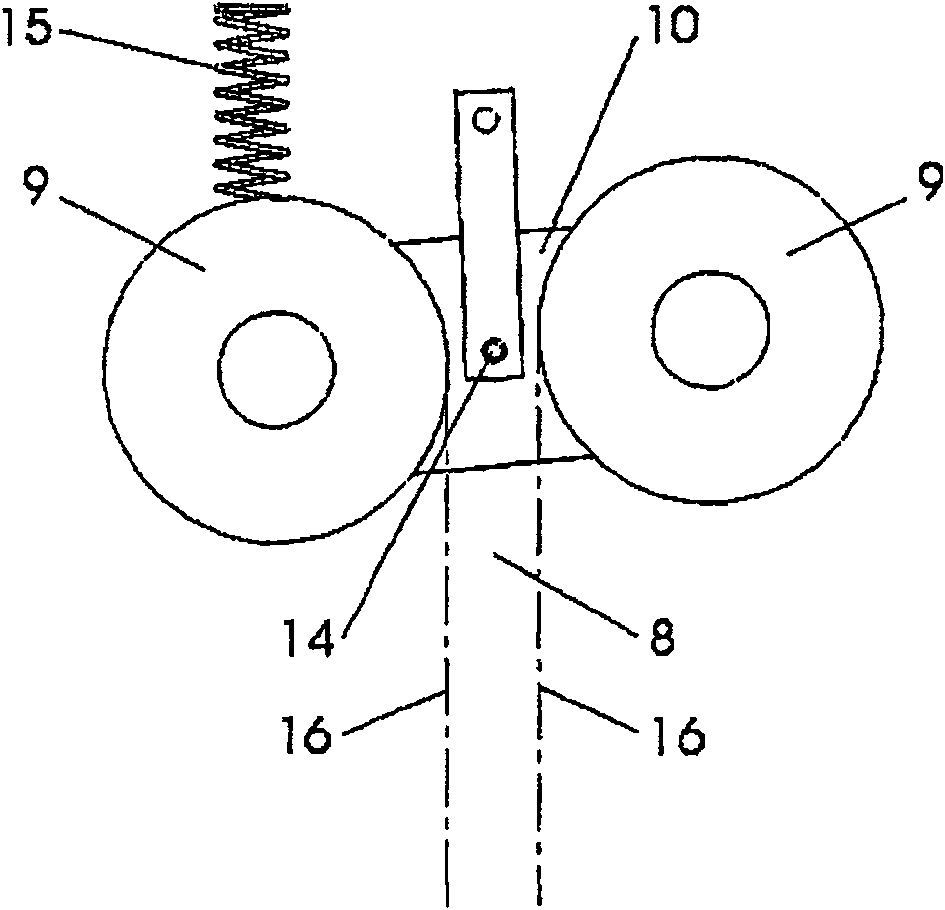
[0031] Such as figure 2 As shown, the swing link 10 is pivotally arranged between the two wheels 9 around the shaft 14 and bears the force of a spring 15, which is supported on a not shown support and is used to rotate the swing link 10, thereby turning the swing link 10 The wheels 9 press against both sides 16 of the rail head 8 . Since the net distance between the two wheels 9 is only slightly smaller than the width of the rail head 8 and the point of application of the spring 15 is far away from the axle 14 of the fork 10, a corresponding leverage is produced, even if the spr...


PUM


Abstract

The invention proposes an emergency braking device for an elevator car, in which a sensor (11) for measuring the speed of the car has a mechanism (13) for detecting excessive speed, which electrically actuates the braking device. In order to be able to reliably determine the speed of the elevator car, it is proposed that two wheels (9) resting against the guide rail (2) are provided for determining said speed. The number of revolutions of each wheel (9) is measured independently by sensors (11), wherein the mechanism (13) triggers emergency braking when one of the sensors (11) reports that an excessive speed has been found. The two wheels (9) can be supported on both sides of a guide rail (2) on a pivotally supported rocker (10), which is prestressed eccentrically by a spring (15). It is also described how the actuating force of the braking device can be reinforced mechanically by means of rollers.

Description

technical field [0001] The invention relates to an emergency braking device for an elevator car. Background technique [0002] The elevator is equipped with a braking device or safety gear for stopping the elevator car at impermissibly high speeds, such as occurs in the event of a control failure or rope breakage. [0003] In known arrangements of this type, a brake or safety gear is actuated by an overspeed governor fixedly installed in the hoistway or in the machine room, which will cause the overspeed governor to rotate when the elevator car is running. For this reason, be provided with a closed speed limiter rope, it walks around the speed limiter (usually at the highest position in the hoistway) at one end, and the other end walks around the tension pulley (usually at the lowest position in the hoistway). The speed-limiting rope is connected to the braking device or safety gear of the elevator car at one point, so that it is driven when the elevator car is running. If...

Claims


Application Information

Patent Timeline
Patent Type & Authority Patents(China)
IPC IPC(8): B66B5/06B66B5/16
CPCB66B5/06B66B5/18
Inventor 弗朗茨·约瑟夫·卡纳伯恩哈德·海德福格尔于尔根·卡纳
Owner WITTUR
Why Eureka
Try Eureka