Supercharge Your Innovation With Domain-Expert AI Agents!

Full port externally gimbal joint

A universal joint and nail head technology, applied in the field of universal joints, can solve the problems of screw falling off and limiting the rotation of the joint.

Inactive Publication Date: 2009-12-23
GENERAL ELECTRIC CO
View PDF6 Cites 0 Cited by
  • Summary
  • Abstract
  • Description
  • Claims
  • Application Information

AI Technical Summary

Problems solved by technology

Previous constructions of universal joints have seen the clevis lugs with holes for receiving the universal screws bend, some so pronounced that the bending not only limits the amount of rotation the joint can accommodate, but also makes the screw off

Method used


Image

  • Full port externally gimbal joint
  • Full port externally gimbal joint
  • Full port externally gimbal joint

Examples


Embodiment Construction

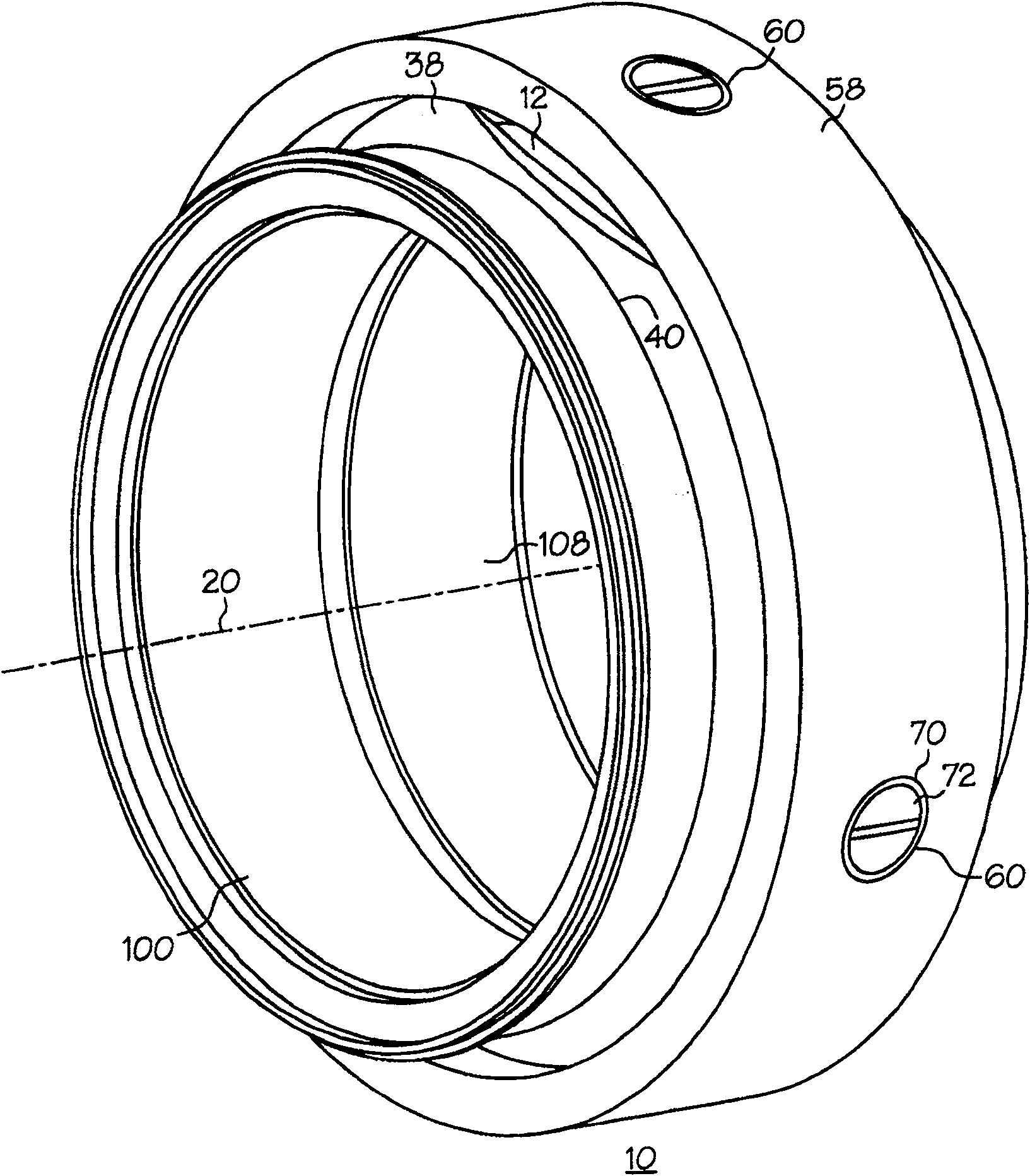
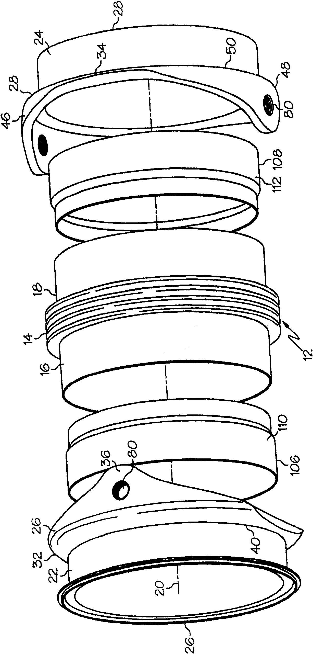
[0017] figure 1 and 3 A universal joint 10 is shown having an annular bellows seal 12 with an intermediate bellows 14 positioned between front and rear cylindrical seal sections 16 and 18 surrounding a centerline 20 of the joint. The front and rear cylindrical sealing sections 16 and 18 are installed in the front and rear sheath annular sections 22 and 24 of the front and rear sheaths 26 and 28 respectively, and the front and rear sheaths 26 and 28 respectively have front and rear U-shaped Clips 32 and 34, the front and rear U-shaped clips 32 and 34 are spaced 90° from each other. The front clevis 32 has first and second front lugs 36 and 38 spaced 180° from each other along the front circumference 40 of the front jacket ring segment 22 . The rear clevis 34 has first and second rear lugs 46 and 48 spaced 180° from each other along the rear circumference 50 of the rear jacket annular segment 24 .

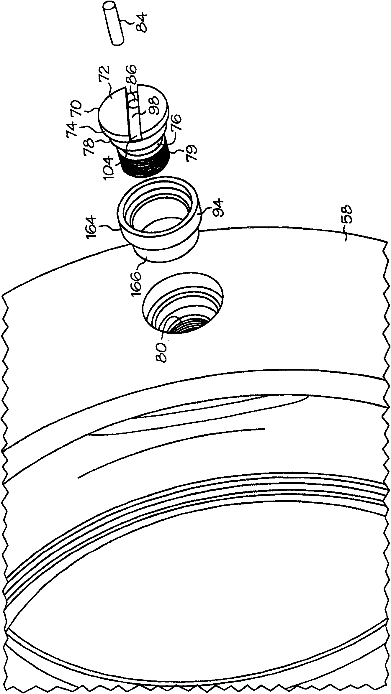
[0018] see again Figure 5 An internally threaded hole 80 is provided throug...


PUM


Abstract

A universal joint (10) has an annular bellows seal (12) mounted within front and rear boots (26, 28) about a joint centerline (20). Front and rear sheaths (26, 28) have clevis (32, 34) with lugs (36, 38, 46, 48) provided on each of said lugs (36, 38, 46, 48) Has threaded holes (80). A collar (58) surrounding the lugs (36, 38, 46, 48) has a plurality of stepped holes (60), each stepped hole (60) being axially aligned with a threaded hole (80). A screw (70) having a head (72) and an inwardly extending shank (76) is inserted into and engages the stepped hole (60). The externally threaded portion (79) of the shank (76) is threaded into the internally threaded hole (80) of each lug. The pins (84) are placed in the pin holes (86) which pass inwardly through the screw head (72) and through the external thread (90) and the internally threaded hole of each externally threaded portion (79) The threaded engagement portion (88) of the internal thread (92) of (80), in one embodiment, is provided with a wear-resistant bushing (94) between the nail head (72) and the collar (58) in the stepped bore.

Description

field of invention [0001] The present invention relates to a joint assembly of pipelines, in particular to a universal joint for flexibly connecting parts of pipelines, especially high-pressure pipelines on aircraft, so that they can rotate mutually at the joints. Background technique [0002] Gas turbine engines generate very high pressure air that is piped to various parts of the engine and / or for other external uses such as in aircraft. High pressure piping typically has flexible joints to accommodate irregular internal passages in the various aircraft and other equipment and machinery in which the piping is used. To meet this requirement, piping components are usually connected by universal joints which provide the necessary flexibility in installing and manipulating the piping during engine operation. Such joints can limit the freedom of movement of the pipes when subjected to operational stresses during engine operation, especially in aircraft. High temperature and p...

Claims


Application Information

Patent Timeline
Patent Type & Authority Patents(China)
IPC IPC(8): F16L27/02F16B39/02F02K1/80F16B7/18F16L27/11
CPCF16L27/0857Y02T50/671F02K1/80F02K1/805F05D2240/55Y02T50/60
Inventor E·J·克里斯蒂安森J·S·希尔A·F·达梅尔
Owner GENERAL ELECTRIC CO
Features
  • R&D
  • Intellectual Property
  • Life Sciences
  • Materials
  • Tech Scout
  • Unparalleled Data Quality
  • Higher Quality Content
  • 60% Fewer Hallucinations
Learn More