Doppler-type ultrasonic flowmeter and ultrasonic flowmeter measuring method
一种多普勒式、流量计测的技术,应用在测量流量/质量流量、流体速度测量、液体/流体固体测量等方向,能够解决不优选、设计及成本不优选、不能充分发挥等问题
- Summary
- Abstract
- Description
- Claims
- Application Information
AI Technical Summary
Problems solved by technology
Method used
Image

Examples
no. 1 Embodiment approach
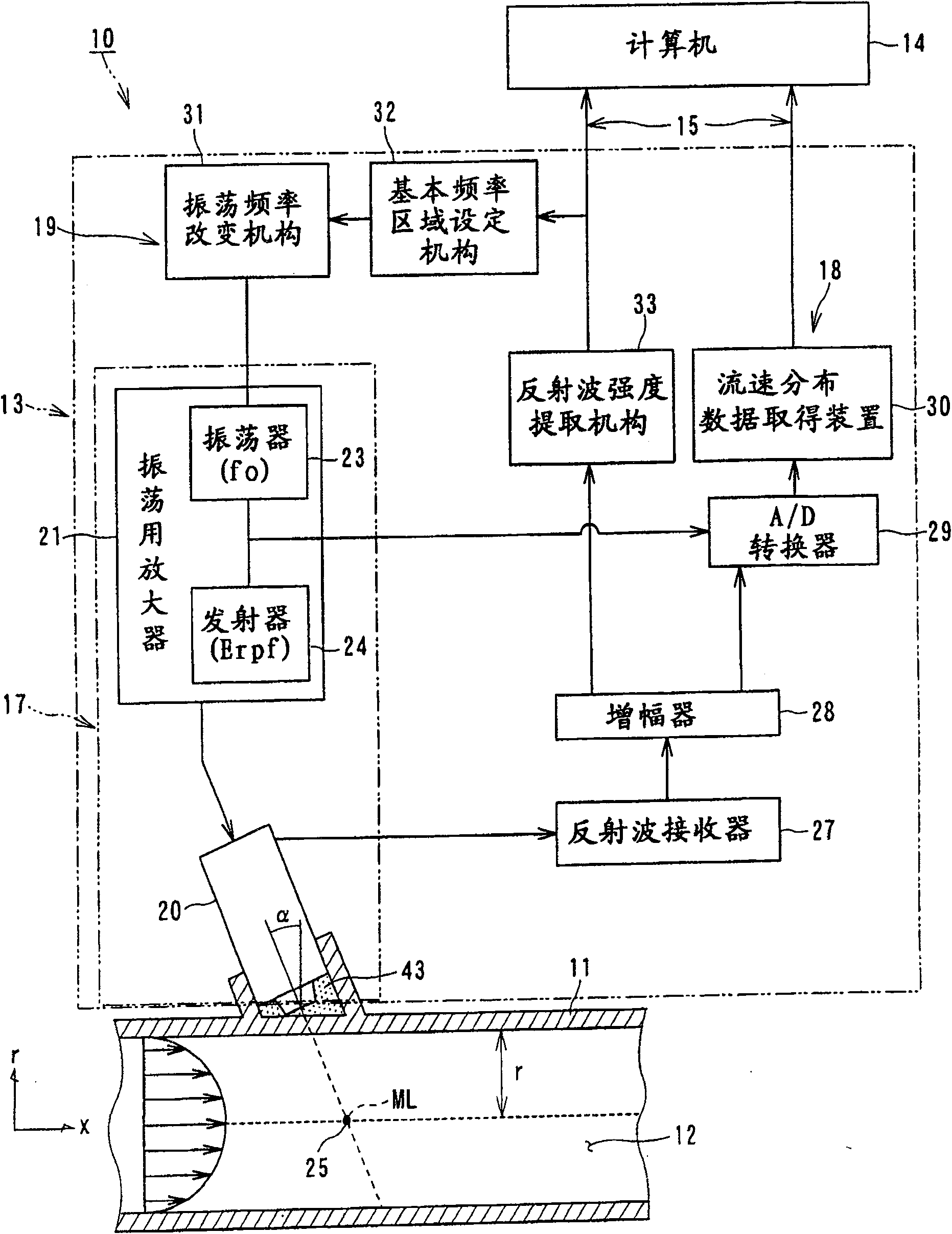
[0126] figure 1 It is a schematic diagram schematically showing the configuration example of the Doppler ultrasonic flowmeter according to the first embodiment of the present invention, that is, the configuration of the Doppler ultrasonic flowmeter 10 .
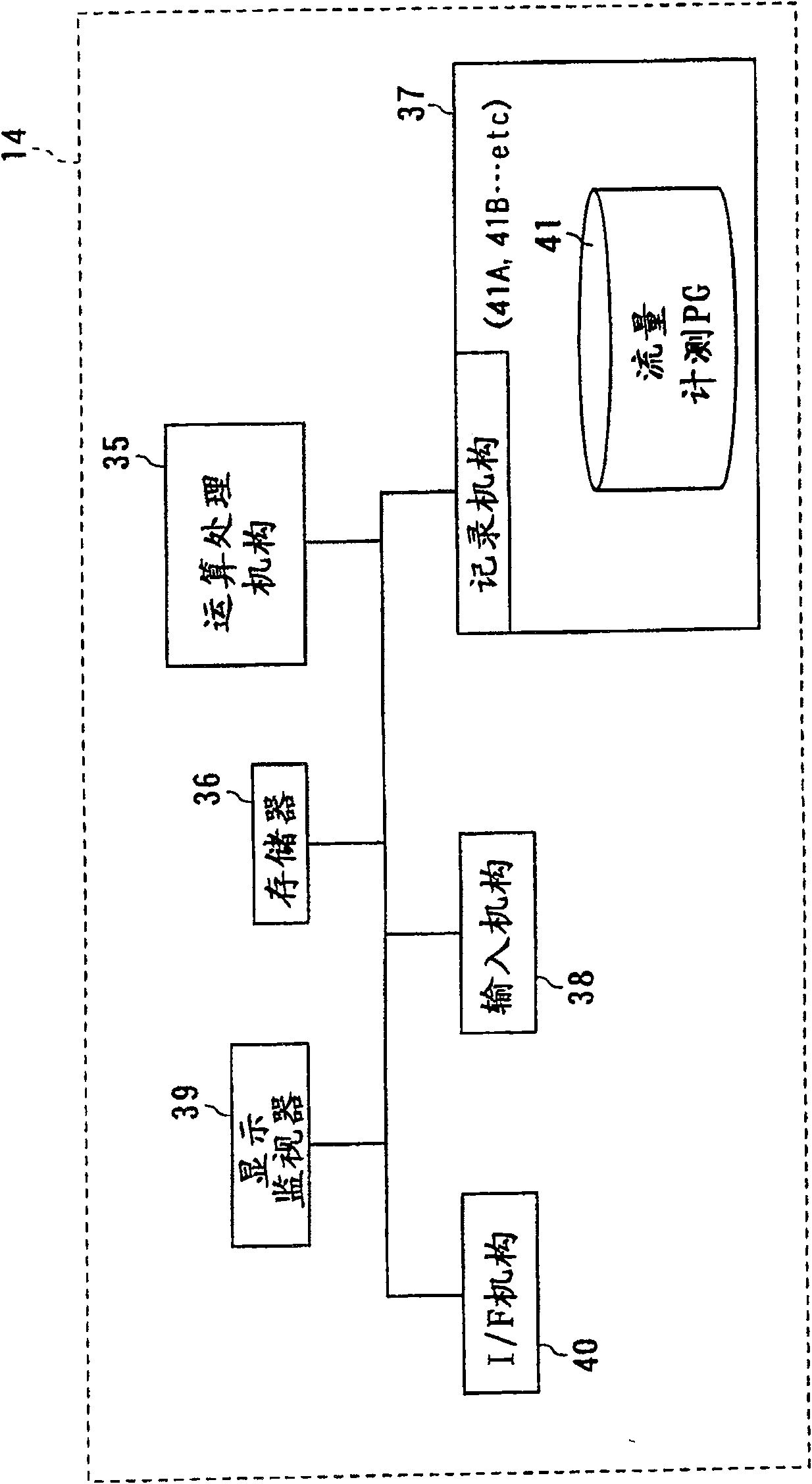
[0127] The Doppler type ultrasonic flowmeter 10 is configured to be able to measure the flow velocity distribution of the fluid to be measured 12 (liquid or gas) flowing in the fluid pipe 11 and to measure the flow rate instantaneously over time. The Doppler type ultrasonic flowmeter 10 has: an ultrasonic flow velocity distribution measurement unit (hereinafter referred to as Udflow unit) 13 for non-contact measurement of the flow velocity of the measured fluid 12 flowing in the fluid piping 11; and a computer 14 for Perform arithmetic processing on the electrical signal (data) output from the Udflow unit 13, perform arithmetic processing on the flow velocity distribution of the measured fluid 12 in order to measure the flow ...
no. 2 Embodiment approach
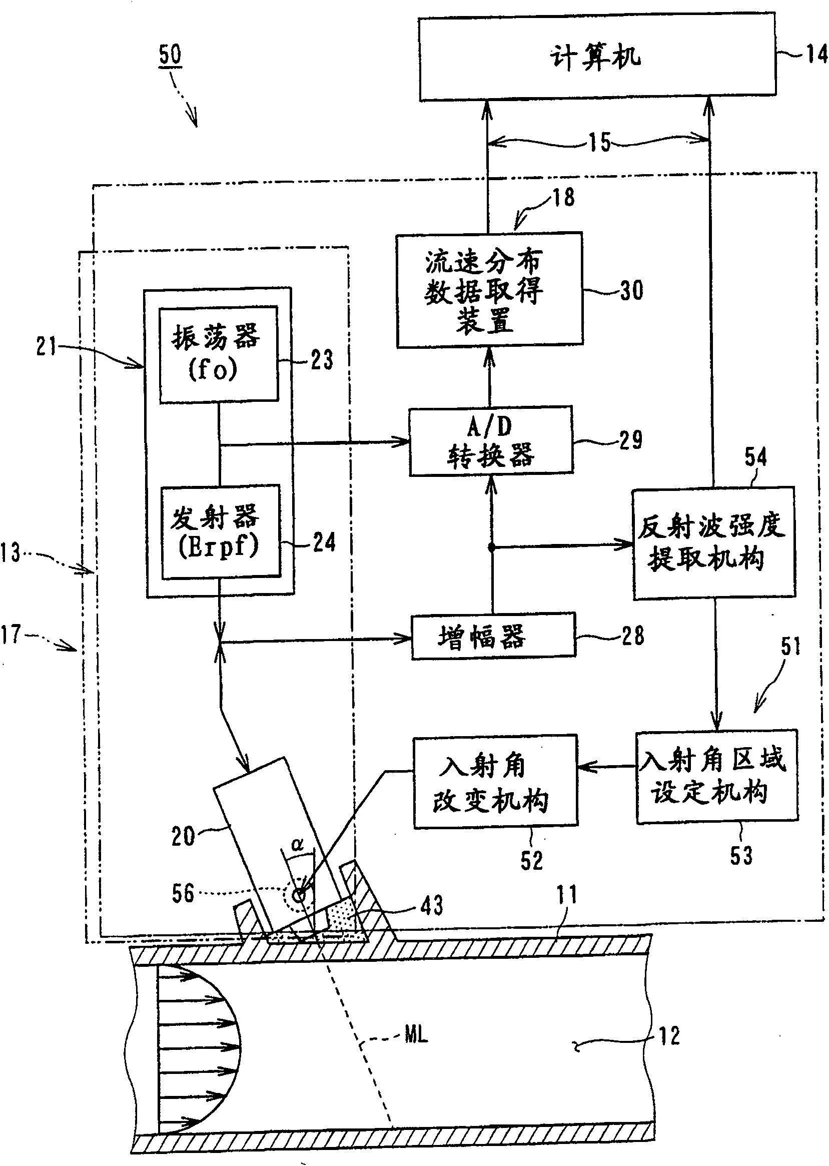
[0147] image 3 It is a schematic diagram schematically showing the configuration example of the Doppler ultrasonic flowmeter according to the second embodiment of the present invention, that is, the configuration of the Doppler ultrasonic flowmeter 50 .
[0148] The Doppler ultrasonic flowmeter 50 is a configuration example of a Doppler ultrasonic flowmeter configured to increase the S / N ratio of reflected waves instead of selecting an optimum frequency of ultrasonic pulses incident into the fluid piping 11 .
[0149] In order to increase the S / N ratio of the reflected wave, it is also possible to change the wall thickness of the fluid pipe 11 to generate a resonant transmission phenomenon, but it is practically impossible to change the wall thickness of the fluid pipe 11 . Therefore, in this configuration example, a method is adopted in which the installation angle of the ultrasonic transducer 20 is changed to have an effect equivalent to that of changing the wall thickness ...
no. 3 Embodiment approach
[0162] Figure 4 to Figure 6 It is a schematic diagram schematically showing the configuration example of the Doppler ultrasonic flowmeter according to the third embodiment of the present invention, that is, the configuration of the Doppler ultrasonic flowmeter 60 .
[0163] Doppler ultrasonic flowmeter 60 as Figure 4 As shown, the Doppler frequency is used to calculate the velocity component V of the measured fluid 12 flowing in the fluid pipe 11 in the direction of the ultrasonic incident angle (entry angle) 2 , based on the calculated Doppler frequency, the flow velocity distribution along the measurement line ML is obtained by the line measurement method, and the flow rate of the measured fluid 12 is calculated.
[0164] In this Doppler type ultrasonic flowmeter 60, the velocity vector V along the ultrasonic line direction (measurement line ML) is calculated from the Doppler frequency 2 , and the velocity vector V 2 Calculate the velocity vector V along the axial direc...
PUM
 Abstract
Description
Claims
Application Information
 - Generate Ideas
- Intellectual Property
- Life Sciences
- Materials
- Tech Scout
- Unparalleled Data Quality
- Higher Quality Content
- 60% Fewer Hallucinations
Browse by: Latest US Patents, China's latest patents, Technical Efficacy Thesaurus, Application Domain, Technology Topic, Popular Technical Reports.
© 2025 PatSnap. All rights reserved.Legal|Privacy policy|Modern Slavery Act Transparency Statement|Sitemap|About US| Contact US: help@patsnap.com