Acoustic Robust Synchronization Signaling for Acoustic Positioning System

a synchronization signal and synchronization signal technology, applied in the field of acoustic positioning methods and systems, can solve the problems of high cost, low cost of toy technology, and inability to provide low-cost toy technology, and achieve the effect of improving the accuracy of the fixing position

Inactive Publication Date: 2008-04-10
QUALCOMM INC
View PDF14 Cites 148 Cited by
  • Summary
  • Abstract
  • Description
  • Claims
  • Application Information

AI Technical Summary

Benefits of technology

[0046]According to one aspect of the present invention there is provided a position detection system for use in association with computing applications, the position detection system containing at least one positional element for attaining a position and a positioning device operative to determine a position of the positional element. The positional element contains at least one first emitter for emitting a substantially continuously modulated acoustic waveform decodable to fix the position, and a second emitter for emitting a synchronization signal. The positioning device contains an arrangement of at least one of a first detector operative to detect the continuously modulated acoustic waveform in a manner permitting fixing of the position and outputting the waveform for computation, in a manner retentive of the position fixing ability; and a second detector operative to detect the synchronization signal. The synchronization signal being a sequence of at least two synchronization sub-signals, each synchronization sub-signal bearing timing data for the continuously modulated acoustic waveform, thereby to improve accuracy of the fixing of the position.

Problems solved by technology

The radio or IR only takes care of the wireless connectivity, that is the signaling issue.
It is relatively uncommon, due to the high cost, to have toys in which one unit can be aware of the location of a second unit.
To provide each of the twenty-two robots with the computing and control power in order to play a game of soccer produces a very expensive and complex solution.
Generally, toy technology has to be provided at low cost and current technology is relatively expensive.
Acoustic—Acoustic devices are relatively expensive.
Only a single unit can be used in the same environment, energy use is relatively high, and the devices are difficult to miniaturize.
The need for sensors adds both to the cost of the final product, and furthermore provides an unnatural restriction on use in that it does not allow the user to use arbitrary planes, such as a cluttered desk surface, as a working platform.
Some of the technologies are limited to two-dimensional locations.
But even those that can manage a third dimension do not currently provide accurate information of the third dimension.
For example a stylus based on electromagnetic detection can be detected when hovering above a screen, but it is not possible to tell accurately how high it is.
There are other drawbacks specific to certain of the technologies.
For instance, IR positioning has difficulties working with direct sun.
Existing acoustic solutions have serious limitations in acoustically noisy environments, in particular in the all-important industrial environment, where ultrasound noise is most common.
Solutions that use wireless protocols as Bluetooth may suffer from protocol collisions, and from interference with other wireless equipment, such as WLAN equipment.

Method used


Image

  • Acoustic Robust Synchronization Signaling for Acoustic Positioning System
  • Acoustic Robust Synchronization Signaling for Acoustic Positioning System
  • Acoustic Robust Synchronization Signaling for Acoustic Positioning System

Examples


Embodiment Construction

[0102]The principles and operation of a positioning system and method according to the present invention may be better understood with reference to the drawings and accompanying description.

[0103]Before explaining at least one embodiment of the invention in detail, it is to be understood that the invention is not limited in its application to the details of construction and the arrangement of the components set forth in the following description or illustrated in the drawings. The invention is capable of other embodiments or of being practiced or carried out in various ways. Also, it is to be understood that the phraseology and terminology employed herein is for the purpose of description and should not be regarded as limiting.

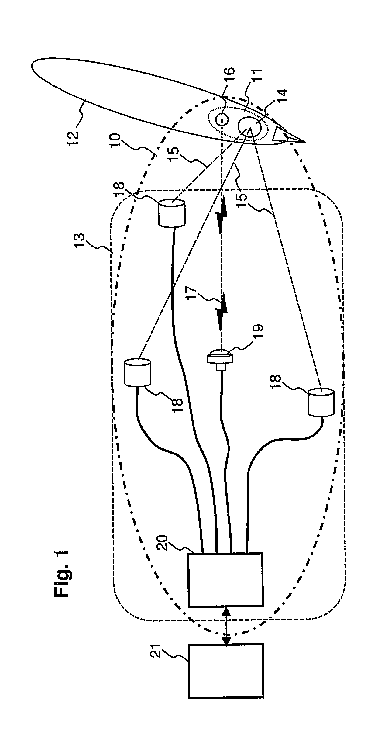
[0104]Reference is now made to FIG. 1, which is a simplified illustration of a positioning system 10 according to a preferred embodiment of the present invention. Positioning system 10 comprises two main parts: a positional assembly 11 mounted on a positional ...


PUM


Abstract

A position detection system comprising positional element and positioning device, wherein the positional element transmits a continuously modulated acoustic waveform and a synchronization signal that is a sequence of at least two synchronization packets, each bearing timing data for the continuously modulated acoustic waveform. Additionally, the synchronization signal uses time hopping to support concurrent positioning of a plurality of positional elements.

Description

FIELD AND BACKGROUND OF THE INVENTION[0001]The present invention relates to an acoustic positioning method and system and, more particularly, but not exclusively to a method and system for synchronization of transmissions between a positional element and a positioning device.[0002]The application of positioning, or location awareness, is commonly divided according to the size of the space in which the positional element should be located.[0003]The space size ranges from the personal area, which range is typically up to 1 meter, the room area which range is typically up to 10 meters, the local area, such as a warehouse, which range is up to 100 meters, and wide area which is typically an open space.[0004]Some applications require positioning in three dimensions. Other applications, typically when the object is known to be located close enough to a known surface, such as the floor, require positioning in two dimensions only, and some applications require only the measurement of the di...

Claims


Application Information

Patent Timeline
Patent Type & Authority Applications(United States)
IPC IPC(8): G01S15/88G06F3/033G01S5/18G01S11/00G01S11/16
CPCG01S5/18G06F3/03545G06F3/0433G01S11/16G06F3/0383G06F3/04166G01S11/00
Inventor ALTMAN, NATHAN
Owner QUALCOMM INC
Why Eureka
Try Eureka