Theftproof Lock

A technology of anti-theft locks and lock cylinders, applied in the field of anti-theft locks, can solve problems such as poor anti-theft effect, and achieve the effect of ensuring anti-theft effect and low price

Inactive Publication Date: 2010-02-10
中国龙亿电子商务有限公司
View PDF5 Cites 0 Cited by
  • Summary
  • Abstract
  • Description
  • Claims
  • Application Information

AI Technical Summary

Problems solved by technology

[0005] In order to improve the shortcomings of the above-mentioned poor anti-theft effect of existing locks, the main purpose of the present invention is to provide an anti-theft lock that can control the lock hole to be in a closed state although it has a lock hole, so as to prevent thieves from inserting and opening foreign objects.

Method used


Image

  • Theftproof Lock
  • Theftproof Lock
  • Theftproof Lock

Examples


Embodiment Construction

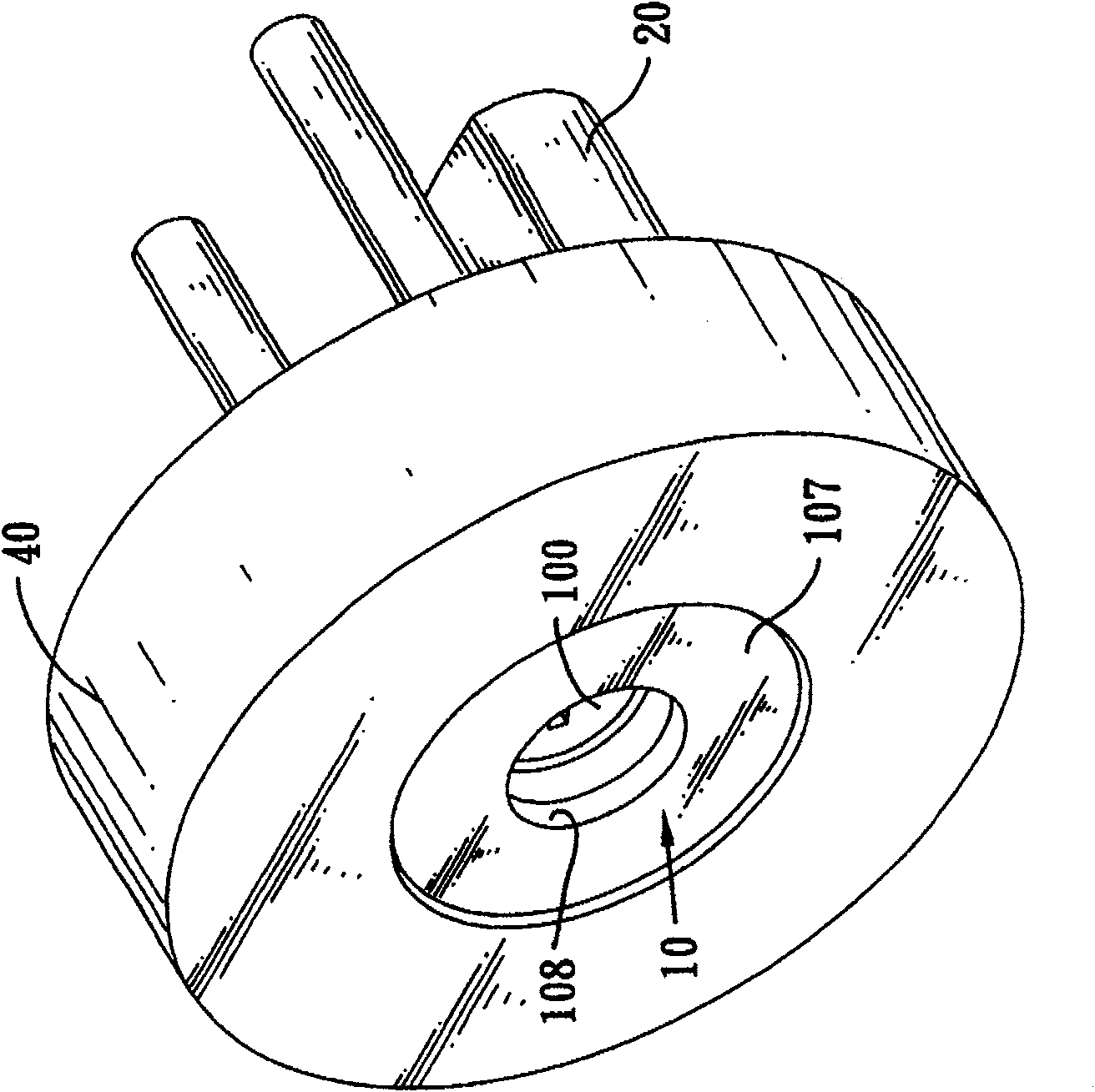
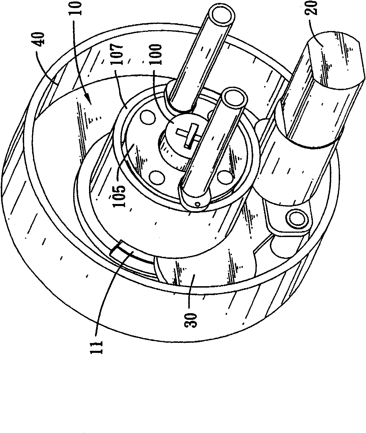
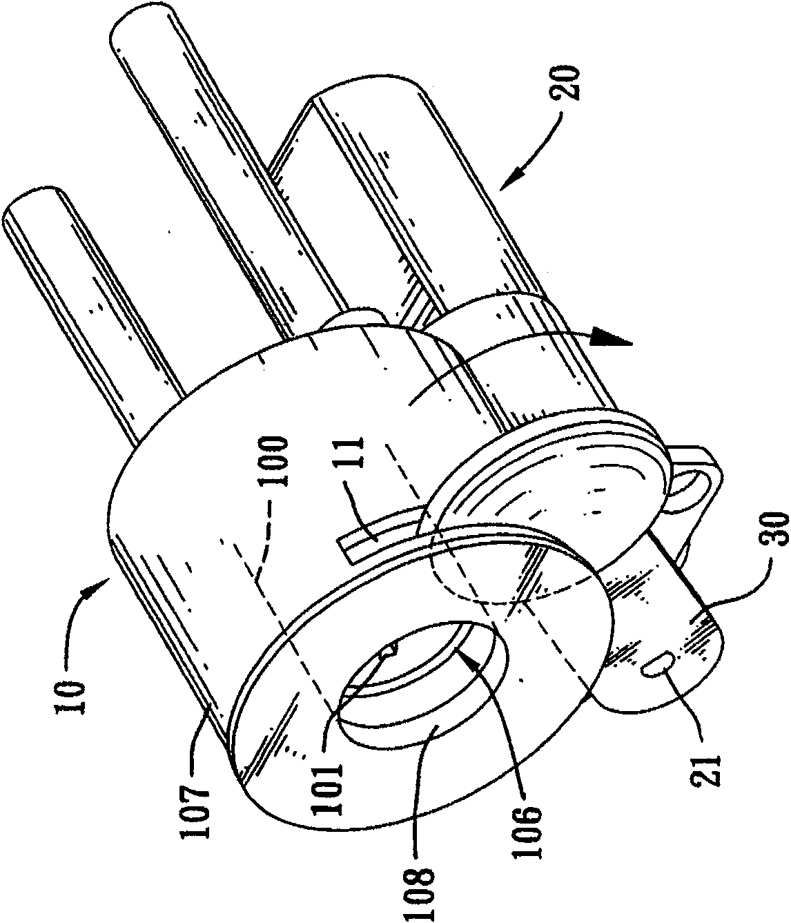
[0029] Please also see Figure 1 to Figure 10 As shown, the anti-theft lock provided by the present invention comprises a cylinder lockset 10, 50 with a lock core 100, 500, a driving element 20, 60 located on one side of the cylinder lockset 10, 50, and a driven element 20, 60 controlled Rotating cover plates 30, 70, the cylinder locks 10, 50 are provided with through grooves 11, 51 for the cover plates 30, 70 to pass through, and the driving elements 20, 60 cooperate with the remote control to control forward rotation or Reverse, when desire to go out, can start drive element 20,60 to rotate, make cover plate 30,70 as Figure 4 , 5 As shown in , 6, the lock holes 101, 501 of the lock cylinders 100, 500 are covered, so that a thief cannot open the lock cylinders 100, 500 by inserting foreign objects, so as to achieve the anti-theft purpose. Again, when desiring to remove the anti-theft state, then use the remote control to control the rotation of the drive elements 20,60 to ...


PUM


Abstract

A burglar-proof lock consists of lock core with lock hole, driving element set at one side of lock, cover plate being controlled by driving element and being cross-set on through hole, through channelpassing through radially on peripheral wall of lock and locating at front position of lock core. It is featured as controlling said driving element by remote control, setting shaft rod at power output end of driving element to link-act with cover plate for controlling cover plate to shield on in front of lock hole or to let lock hole be at through state.

Description

【Technical field】 [0001] The invention relates to a lock, which is an anti-theft lock that can be used in the field of buildings and can prevent thieves from inserting and opening keys and the like. 【Background technique】 [0002] Locks are the basic tools for people to protect property safety. Taking locks installed on residential gates as an example, the types of locks can be roughly divided into two types: manual and induction. The door tab is retracted (or can be retracted by the handle control), and the room can be entered. In order to improve its anti-theft function, the structure of this kind of manual lock is becoming more and more complicated. There are two-stage or even three-stage types. Insert and open, its anti-theft effect is still to be considered. [0003] The so-called inductive type is to install an inductive host on the door, and then use an inductive card to open it. The cooperation between the inductive host and the inductive card can be roughly divide...

Claims


Application Information

Patent Timeline
Patent Type & Authority Patents(China)
IPC IPC(8): E05B17/18
Inventor 王跃霖
Owner 中国龙亿电子商务有限公司
Why Eureka
Try Eureka