Threading holder of sewing machine

A technology of clamping mechanism and sewing machine, which is applied to the mechanism of cutting thread in sewing machine, sewing machine components, sewing equipment, etc., and can solve the problems of complex structure of upper thread clamping components

Active Publication Date: 2010-02-24
BROTHER KOGYO KK
View PDF5 Cites 0 Cited by
  • Summary
  • Abstract
  • Description
  • Claims
  • Application Information

AI Technical Summary

Problems solved by technology

In this way, a large number of components such as a plurality of connecting rods for guiding the linear movement direction of the wire clamping member, a member supporting the plurality of

Method used


Image

  • Threading holder of sewing machine
  • Threading holder of sewing machine
  • Threading holder of sewing machine

Examples


Example Embodiment

[0019] Refer below Figure 1 ~ Figure 12 The embodiment of the present invention is explained.

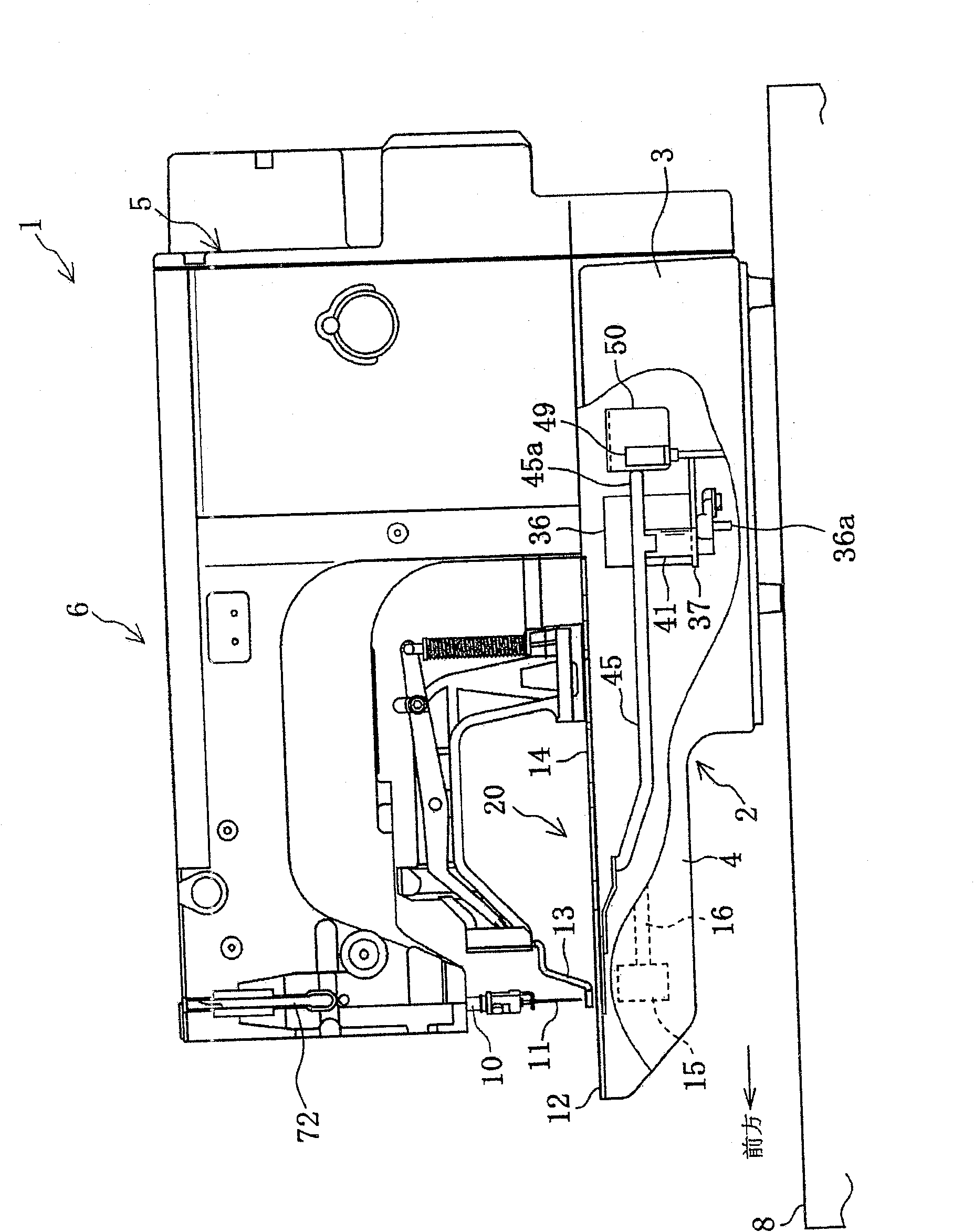
[0020] Such as figure 1 As shown, the electronic bar tacking reinforcement sewing machine 1 is set on the workbench 8. The electronic bar tacking sewing machine 1 is composed of a bottom plate 2, a pillar 5 extending upward from the rear end of the bottom 2, and an arm 6 extending forward from the upper end of the pillar 5. The arm 6 and the bottom The upper part of section 2 is opposite. The length of the bottom plate portion 2 and the arm portion 6 is relatively long in the front and rear direction, and the length in the left and right direction is relatively short.

[0021] An operation panel 9 is installed on the workbench 8. The operation panel 9 is equipped with a liquid crystal display 9a, a selection switch 9b for selecting the type of bar tacking reinforcement stitch and the pattern of the bar tacking reinforcement stitch, and setting whether to set the end of the upper thre...


PUM


Abstract

The invention relates to a threading holder of sewing machine. A second thread clamping plate 22 rotates among a starting position, a clamping position and a releasing position. The starting positionof the second thread clamping plate 22 is the position where its thread hole 22b overlaps the needle hole 12a of the throat plate 12. When the second thread clamping plate 22 is at the starting position, the needle 11 descends and enters to the thread hole 22b from the needle hole 12 and the needle 11 ascends and emerges to from the needle hole 12a to the thread hole 22b, and when the needle 11 emerges out, the thread end section 7a of thread 7 is in its thread hole 22b of the second thread clamping plate 22. The clamping position is the position where its thread hole 22b overlaps the inferiorof the first thread clamping plate 21. When the second thread clamping plate 22 rotates to the clamping position, the thread end section 7a is clamped between the second thread clamping plate 22 andfirst thread clamping plate 21. A releasing position is the position where the thread hole 22b is locally opened. When the second thread clamping plate 22 moves to the releasing position, the clamp ofthe thread end section 7a is released.

Description

technical field [0001] The present invention relates to an upper thread clamping mechanism of a sewing machine which releasably clamps the thread end of an upper thread extending from an eyelet of a sewing needle on the lower side of a needle plate installed on a base plate. Background technique [0002] In various sewing machines such as bartack sewing machines that form bartack stitches, depending on the type of fabric to be processed and the type of needle thread, the thread take-up lever rises at the beginning of sewing and the needle thread is often pulled out of the needle hole. eyes protruding. Therefore, there is a proposal to hold the upper thread on the lower side of the needle plate at the beginning of sewing, and to prevent skipped stitches by continuing to hold the upper thread until several stitches are formed. This clamping of the upper thread is carried out when the sewing needle descends from the uppermost position and passes through the needle hole of the ...

Claims


Application Information

Patent Timeline
IPC IPC(8): D05B65/06
Inventor 位田敬竹村徹
Owner BROTHER KOGYO KK
Why Eureka
Try Eureka