Automatic double-clutch engine gear arm

A dual-clutch and engine technology, applied in the field of shifting arms, can solve the problems of inability to control the clutch clutch, difficult operation, damage to the engine, etc., and achieve the effects of stable and reliable work, simple operation and low manufacturing cost.

Inactive Publication Date: 2010-03-10
胡光宇
View PDF4 Cites 0 Cited by
  • Summary
  • Abstract
  • Description
  • Claims
  • Application Information

AI Technical Summary

Problems solved by technology

When the driver is operating the motorcycle to change gears, he needs to cooperate with his hands and feet. While manipulating the clutch handle with his hands, he also uses his feet to step on the gear shift pedal to change gears. Large, the engine is often damaged due to improper operation
Therefore, it is necessary to change the clutch operation mode of this engine into an automatic clutch, eliminate the step of operating the clutch by hand alone, and make the driving simpler and easier. At present, the shift arm of the manual clutch engine mainly consists of the shift shaft 1 and its The positioning spring 2 of the suit, the first shifting plate 3, the limit plate 6, the return spring 4 and the snap ring are formed (such as figure 1 As shown), it only has the function of shifting gears, and cannot operate the clutch to achieve clutching

Method used


Image

  • Automatic double-clutch engine gear arm
  • Automatic double-clutch engine gear arm
  • Automatic double-clutch engine gear arm

Examples


Embodiment Construction

[0015] The present invention will be further explained below in conjunction with the drawings and embodiments:

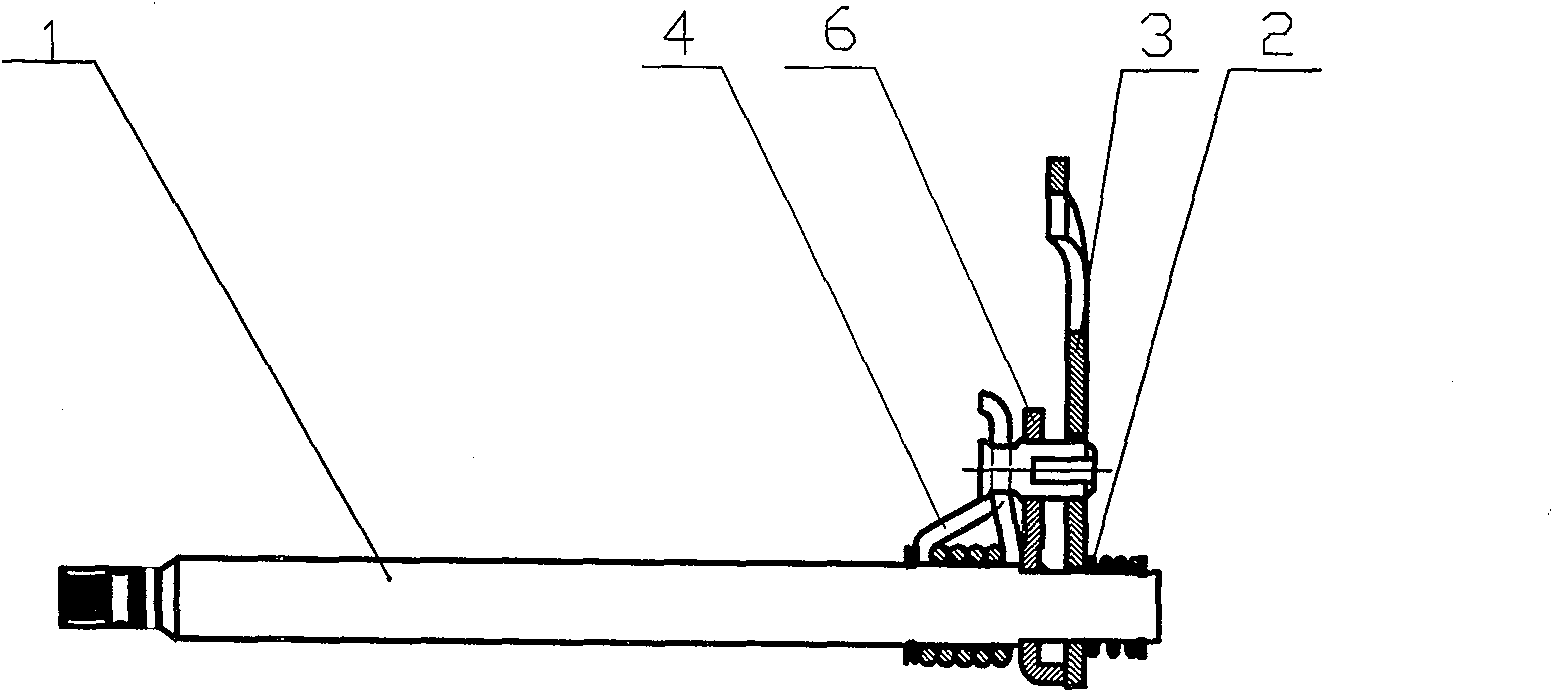
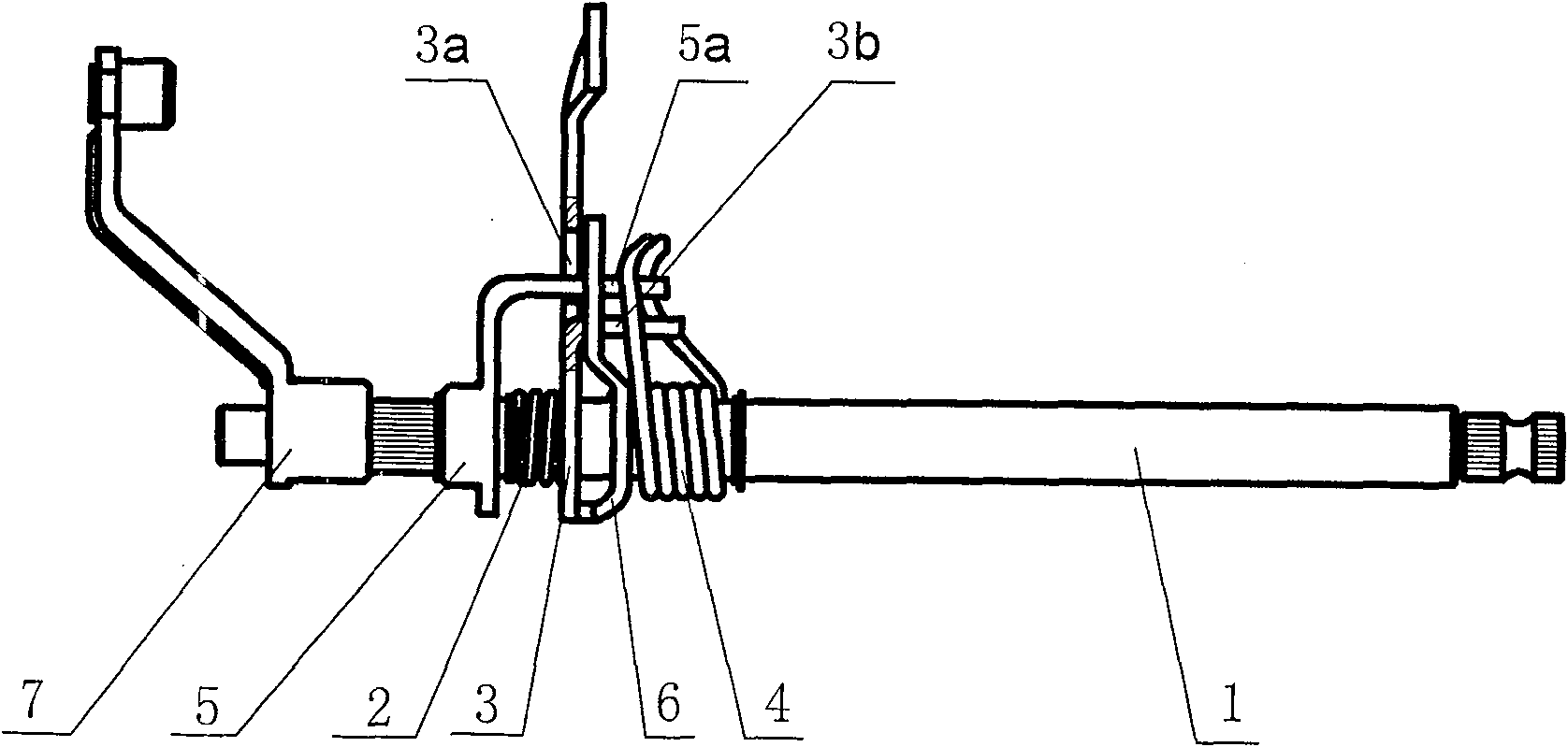
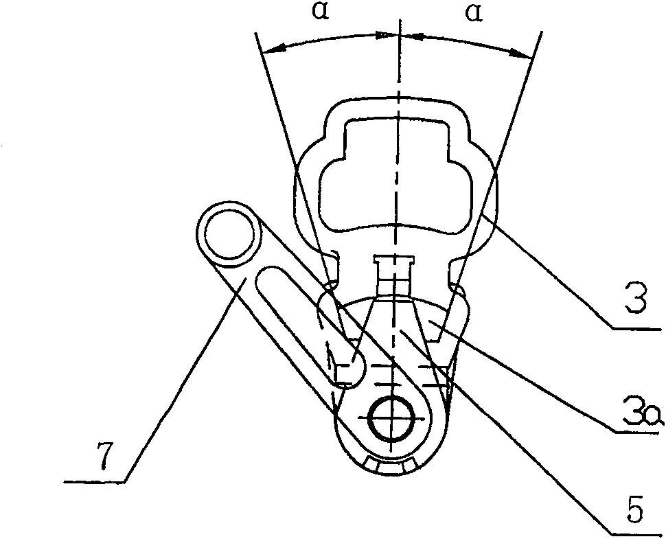
[0016] Such as figure 2 As shown, the present invention is mainly composed of a shift shaft 1, a control arm 7, a second shift plate 5, a positioning spring 2, a first shift plate 3, a limit plate 6, a reset spring 4, a washer and a snap ring. A shifting plate 3 is looped with the shift shaft 1, a slot 3a with a folding arm 3b at the lower edge is provided in the middle, and the folding arm 3b of the first shifting plate 3 extends between the two clamping feet of the reset spring 4. The spring 4 is locked by a snap ring; the second shift plate 5 has an "L" shaped folding arm 5a and is welded to the shift shaft 1, and the folding arm 5a of the second shift plate 5 passes through the slot of the first shift plate 3. 3a and extend between the two clamping feet of the reset spring 4. The positioning spring 2 is press-fitted between the second shift plate 5 and the first s...


PUM


Abstract

This invention is automatic double clutches engine gear change arm. There are locating reed, first driving board, spacing board, reset reed, gasket and clasp on the gear changing shaft. The said firstdriving board is active cased on the gear changing shaft. The spacing board and gear changing shaft are welded together. The slot, which bottom edge has bend arm, is set on the middle part of the said first driving board. The bend arm is set between the two clamping feet of reset reed. The reset reed is locked by clasp. The 'L' shaped second driving board is welded on the gear changing shaft outside locating reed. The bend arm of second driving board passes through slot and extends into two clamping feet of reset reed. The reset reed is arranged between first and second driving boards. The gear changing shaft outside the second driving board is arranged with operating arm through spline. This invention can automatically separate the clutch when changing gear.

Description

Technical field [0001] The invention relates to a motorcycle transmission operating mechanism, in particular to a shift arm used for an automatic dual-clutch engine of a motorcycle. Background technique [0002] At present, the clutch mode of almost all motorcycle CG engines on the market is manual clutch mode. When the motorcycle changes gears while driving, the driver must manually manipulate the disconnect clutch before the engine can shift gears. When the driver is manipulating the motorcycle to shift gears, he must cooperate with his hands and feet. While manipulating the clutch handle by hand, he uses his foot to step on the shift pedal to shift gears. This is very complicated and cumbersome, and requires the driver to have sufficient experience to proceed smoothly. It is difficult for novices to operate. The engine is often damaged due to improper operation. Therefore, it is necessary to change the clutch operation mode of this engine to automatic clutch, eliminate the st...

Claims


Application Information

Patent Timeline
Patent Type & Authority Patents(China)
IPC IPC(8): F16H59/02
Inventor 胡光宇
Owner 胡光宇
Why Eureka
Try Eureka