Novel butterfly spool for forming near linear relation between through flow and spool corner and butterfly valve thereof

A technology that approximates a straight line and a linear relationship. It is applied in the direction of valve lifts, valve devices, and engine components. It can solve problems such as lack of rotation angle detection devices, long adjustment time, and unstable adjustment, and achieve simple quantitative relationships and excellent sealing effects. Effect

Inactive Publication Date: 2007-07-18
杨耀德
View PDF0 Cites 3 Cited by
  • Summary
  • Abstract
  • Description
  • Claims
  • Application Information

AI Technical Summary

Problems solved by technology

There is a non-linear relationship between the flow rate of the valve (hereinafter referred to as the flow rate) and the rotation angle of the valve plate. The change of the rotation angle has little effect on the flow rate of the valve, but it will cause a large change in the flow rate at the end of the process; and vice versa
[0004] Obviously, although the flow control adjustment method of ordinary butterfly valves is simple, due to the complex nonlinear linear relationship between the passing flow and the valve disc rotation angle, the passing flow cannot be adjusted uniformly, and the flow adjustment is mainly close to the fully closed position of the valve disc. The area is carried out, because the closer to the fully closed position, the adjustment range of the flow is larger, making the adjustment and control of the flow very unstable
[0005] Especially for butterfly valves equipped with automatic control equipment, the automatic control equipment generally does not have a rotation angle detection device (or function), and its corresponding relationship between the adjustment amount of the rotation angle of the valve plate at each position and the adjustment amount of the flow rate According to a simple linear relationship, it is easy to cause problems such as long adjustment time and unstable adjustment.
In order to solve this problem, some manufacturers have added complex intelligent control mechanisms or control programs to the valve, as well as the corresponding transmission system, but this has greatly increased the cost, size and weight of the valve control part and the corresponding maintenance difficulty

Method used


Image

  • Novel butterfly spool for forming near linear relation between through flow and spool corner and butterfly valve thereof
  • Novel butterfly spool for forming near linear relation between through flow and spool corner and butterfly valve thereof
  • Novel butterfly spool for forming near linear relation between through flow and spool corner and butterfly valve thereof

Examples


Embodiment Construction

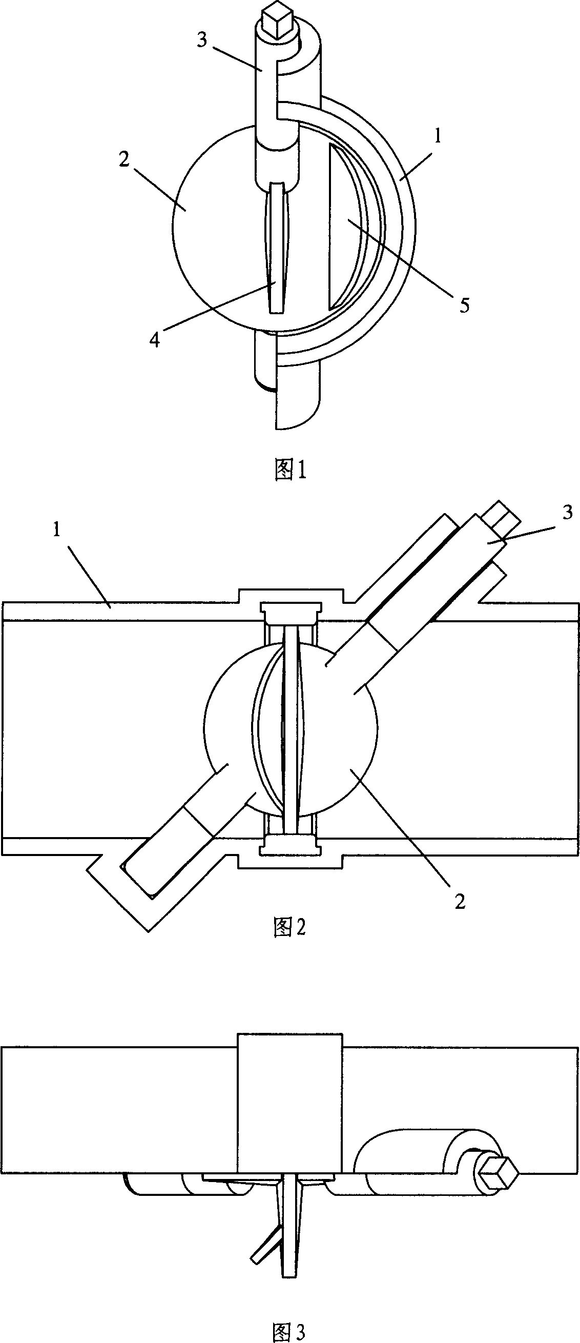
[0028] The present invention will be further described below in conjunction with the accompanying drawings.

[0029] Fig. 1, Fig. 2 and Fig. 3 are the left view, front view and top view of the butterfly valve of the present invention in a fully closed state, respectively. The circumference of the valve plate 2 is in close contact with the gasket in the housing 1, and fluid cannot pass through at this moment. In the fully closed state, since the rotating shaft of the butterfly valve plate of the present invention does not pass through the outer edge of the valve plate 2, it will not interfere with the sealing gasket of the valve plate 2, which improves the assembly conditions and stress conditions of the valve plate, so the valve plate of the present invention The sealing performance is obviously better than ordinary butterfly valves.

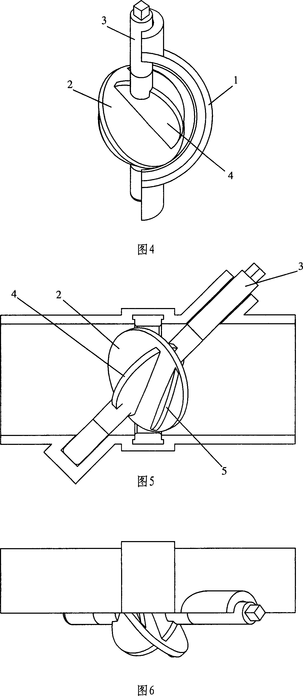
[0030] The invention changes the position of the rotating shaft of the valve plate in the ordinary butterfly valve. In this embodiment, the a...


PUM


Abstract

The invention provides a novel butterfly valve core, comprising a valve plate, and characterized in that: a. the axis of its rotating shaft passes through the center of the valve plate and makes a certain dip with the plane of the valve plate; b. one or two sides of the surface of the valve plate are provided with one or several auxiliary plates. And it can implement an approximate linear relation between flow and valve core corner, thus implementing a simple quantization relation between flow and valve core corner, so as to control change of flow. And the invention also provides a butterfly valve using it.

Description

technical field [0001] The present invention relates to the valve body technology, in particular to a novel butterfly valve core which can control the valve body of the butterfly valve core so that the passing flow and the rotation angle of the butterfly valve core have an approximate linear linear relationship, and the application of the valve core to quickly , A new type of butterfly valve that can control the flow through the valve stably and accurately. Background technique [0002] At present, the valve body of the existing butterfly valve core, such as a butterfly valve, is generally composed of a housing, a butterfly valve plate, a rotating shaft assembly and its operating mechanism. Among them, the operating mechanism changes the resistance characteristics or flow coefficient of the valve by adjusting the rotation angle of the valve plate, so that the flow through the valve changes accordingly to achieve the purpose of controlling the flow parameters in the pipeline ...

Claims


Application Information

Patent Timeline
Patent Type & Authority Applications(China)
IPC IPC(8): F16K1/36F16K1/48F16K1/22
Inventor 杨耀德
Owner 杨耀德
Why Eureka
Try Eureka