
Method for mapping service flow to service transmission path and optical network terminal

A technology for optical network terminal and service transmission, applied in the field of optical network, can solve the problem of unsupported, unable to meet the QoS requirements of subdivided services, etc.

Active Publication Date: 2012-08-15
HUAWEI TECH CO LTD
View PDF0 Cites 0 Cited by
  • Summary
  • Abstract
  • Description
  • Claims
  • Application Information

AI Technical Summary

Problems solved by technology

[0053] The technical problem to be solved by the present invention is to provide a method for mapping service flows to service transmission channels in a passive optical network system, which overcomes that the service flow mapping method in the prior art does not support the DSCP domain of the VLAN ID, IP layer, and IP Or the MAC source address, IP or MAC destination address, protocol type, TCP / UDP port number or other characteristics of the message map the service flow to different service transmission channels, so it cannot meet the shortcomings of the subdivided service QOS requirements

Method used


Image

  • Method for mapping service flow to service transmission path and optical network terminal
  • Method for mapping service flow to service transmission path and optical network terminal
  • Method for mapping service flow to service transmission path and optical network terminal

Examples


Embodiment Construction

[0107] Below in conjunction with accompanying drawing and embodiment the present invention is described in further detail:

[0108] The message feature is the value of a certain feature field in the message data frame. For example, for the IP address 10.11.1.1, the value of the message feature is 4 bytes (00001010, 00001011, 00000001, 00000001). The packet feature offset byte count is the offset byte count between the packet feature field and the packet (data frame) header. For example, the offset byte count between the source IP address field and the Ethernet packet header is 26.

[0109] In order to overcome the disadvantage that the existing technology cannot support the mapping of service flows according to the message characteristics of different services, the present invention first determines the message characteristics of different services and the number of offset bytes of the message characteristics, and saves them in the optical network terminal , for example, we ca...


PUM


Abstract

The method comprises: optical network terminal saves message features of different services, and after receiving service stream, maps the service stream matching the message feature into the appointed service transmission channel, or maps the service stream into the appointed service transmission channel and meanwhile re-labels the priority of the service stream, or re-labels the priority of service stream; according to the re-labeled priority, the optical network terminal maps the service stream into the service transmission channel. The optical network terminal thereof comprises: an optical network protocol processing module comprising a universal service stream mapping module and a service processing module.

Description

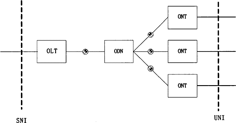
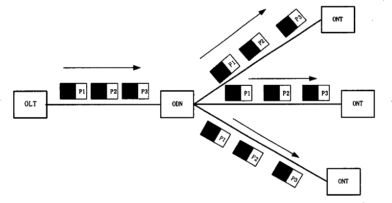
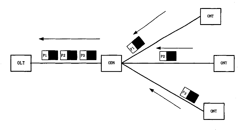
technical field [0001] The invention relates to the technical field of optical networks, in particular to a method for mapping service flows to service transmission channels and an optical network terminal in the technical field. Background technique [0002] The current broadband access technology is mainly divided into copper wire access technology and optical access technology. An access network implemented by an optical access technology is called an optical access network (OAN, optical access network). PON is an implementation technology of optical access network. PON technology is a point-to-multipoint optical access technology, such as figure 1 As shown, the PON system consists of an optical line terminal (OLT, Optical Line Terminal), an optical distribution network (ODN, Optical Distribute Network), and an optical network unit (ONU, Optical Network Unit), wherein: [0003] OLT: Provides a network side interface (SNI, Service Node Interface) for the OAN, and connect...

Claims


Application Information

Patent Timeline
Patent Type & Authority Patents(China)
IPC IPC(8): H04L12/56H04L29/12H04Q11/00
Inventor 牛乐宏欧阳伟龙
Owner HUAWEI TECH CO LTD
Learn More