Predistorting device and method

A technology of pre-distortion and pre-distortion, which is applied in parts of amplification devices, digital transmission systems, electrical components, etc., can solve problems such as transmission channel compensation, pre-distortion coefficient error, and difference, and achieve pre-distortion and pre-distortion coefficient exact effect

Inactive Publication Date: 2007-08-22
HUAWEI TECH CO LTD
View PDF0 Cites 38 Cited by
  • Summary
  • Abstract
  • Description
  • Claims
  • Application Information

AI Technical Summary

Problems solved by technology

In the prior art, the feedback channel is assumed to be ideal. As a result, these errors in the feedback channel are converted into the characteristics of the transmission channel, resulting in errors in the extracted pre-distortion coefficients, so t

Method used


Image

  • Predistorting device and method
  • Predistorting device and method
  • Predistorting device and method

Examples


Embodiment Construction

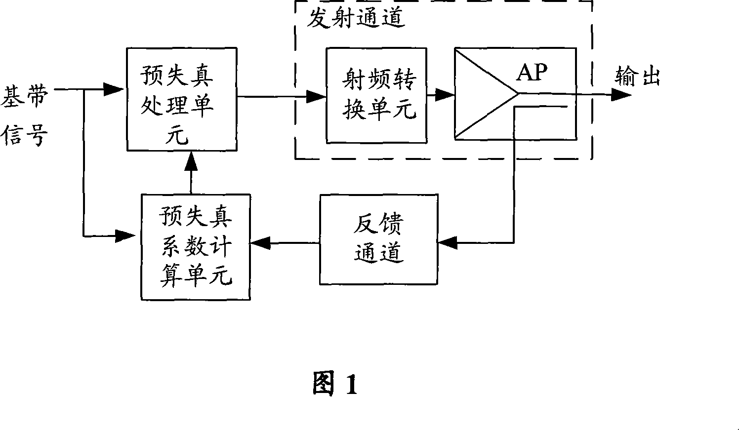
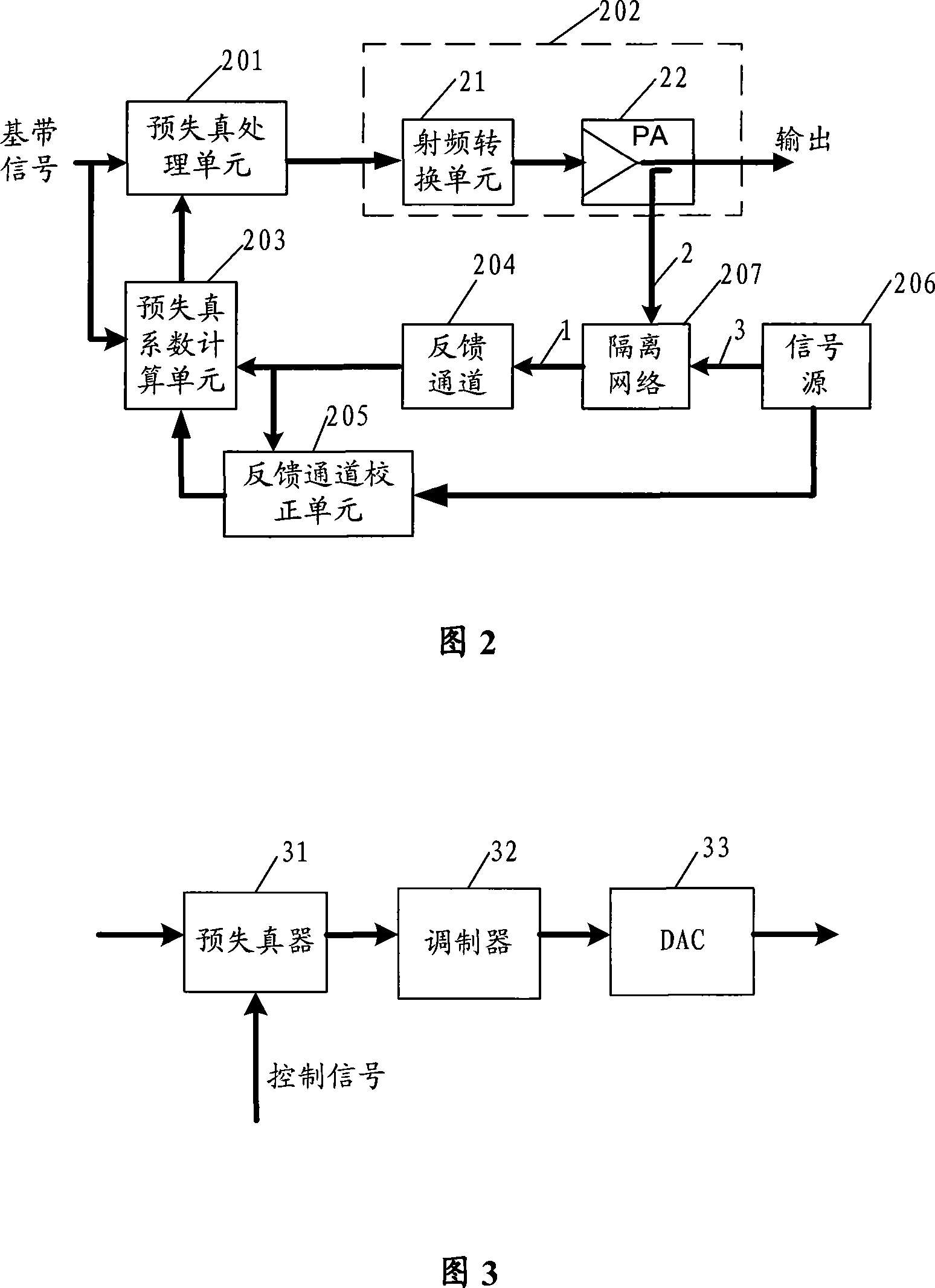
[0025] The embodiment of the present invention mainly obtains the non-ideality of the feedback channel, and deducts the influence of the non-ideality of the feedback channel when calculating the pre-distortion coefficient, so that the pre-distortion coefficient only corresponds to the non-ideality of the transmission channel, and is not related to the non-ideality of the feedback channel. Ideality is irrelevant, so that the distortion of the entire transmit channel is well compensated by the predistortion process.

[0026] In order to enable those skilled in the art to better understand the solutions of the present invention, embodiments of the present invention are now described with reference to the accompanying drawings. First of all, let me explain that the transmission channel including the power amplifier can be expressed as y(t)=f(x(t)), x(t) is the input signal of the transmission channel, t is time, and y(t) is the transmission channel. The channel output, f is a nonl...


PUM


Abstract

A pre-distorting method deducts pre-distortion coefficient of feedback channel in pre-distortion coefficient obtained by existing technique to make pre-distortion treatment of input signal be distortion complete complementation of emission channel for raising accuracy of pre-distortion.

Description

technical field [0001] The present invention relates to the field of communication technology, in particular to a predistortion device and method. Background technique [0002] So far, a variety of techniques for linearizing the power amplifier (PowerAmplifier, PA) in the transmitter of the mobile communication system have been studied, and the main techniques are feedforward and predistortion techniques. The forward feedforward method has been widely used However, the stability of this method is not good, and the equipment is very complicated. Therefore, the predistortion technique becomes an ideal technique for linearizing the power amplifier. [0003] As shown in Figure 1, the pre-distortion technology currently used is to pre-distort the transmitted signal first to compensate for the distortion of the transmission channel including the power amplifier. signals are the same. This requires that the pre-distortion must be completely complementary to the distortion of the...

Claims


Application Information

Patent Timeline
IPC IPC(8): H04L25/49
CPCH03F1/3247H04L27/368
Inventor 叶四清
Owner HUAWEI TECH CO LTD
Why Eureka
Try Eureka