
Sleeping state improving system, and sleeping state improving method

A sleep state, sleep technology, applied to devices that cause changes in perception states, heating and ventilation control systems, heating and ventilation safety systems, etc., can solve problems such as heaviness, inability to use presumed sleep stage devices, and difficulty in improving sleep

Inactive Publication Date: 2007-09-12
DAIKIN IND LTD
View PDF1 Cites 16 Cited by
  • Summary
  • Abstract
  • Description
  • Claims
  • Application Information

AI Technical Summary

Problems solved by technology

[0004] However, in the prior art, there is a tendency that when the user goes out, it is difficult to improve the sleep state of the user.
That is, in the prior art, in order to improve the sleep state of the user, it is necessary to have a device for estimating the sleep stage, but because the device for estimating the sleep stage is bulky and heavy, it is difficult to carry
For this reason, when the user goes out, the device for estimating the sleep stage cannot be used, and there is a tendency that the user's sleep state is difficult to improve when the user goes out.

Method used


Image

  • Sleeping state improving system, and sleeping state improving method
  • Sleeping state improving system, and sleeping state improving method
  • Sleeping state improving system, and sleeping state improving method

Examples


no. 1 approach —

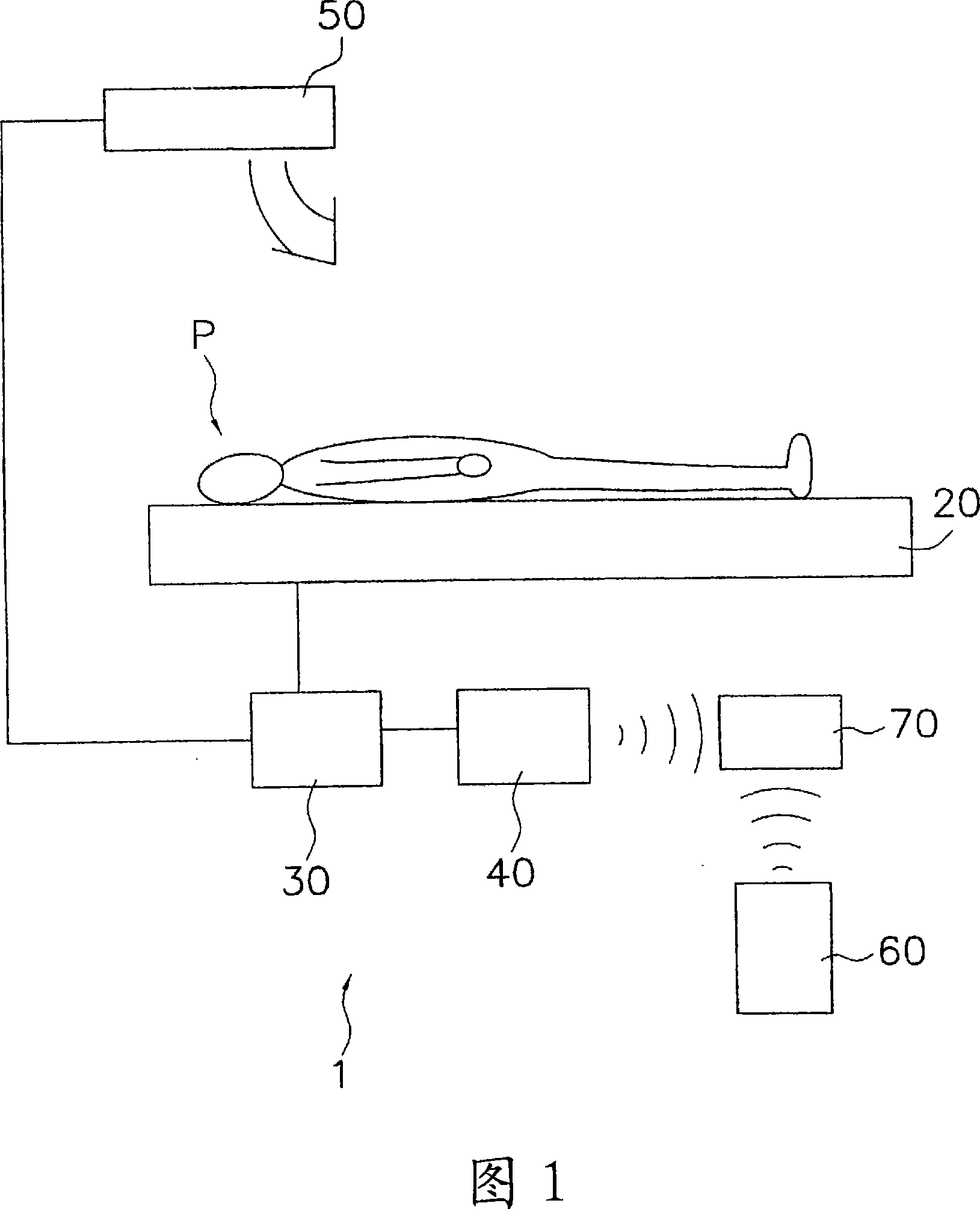
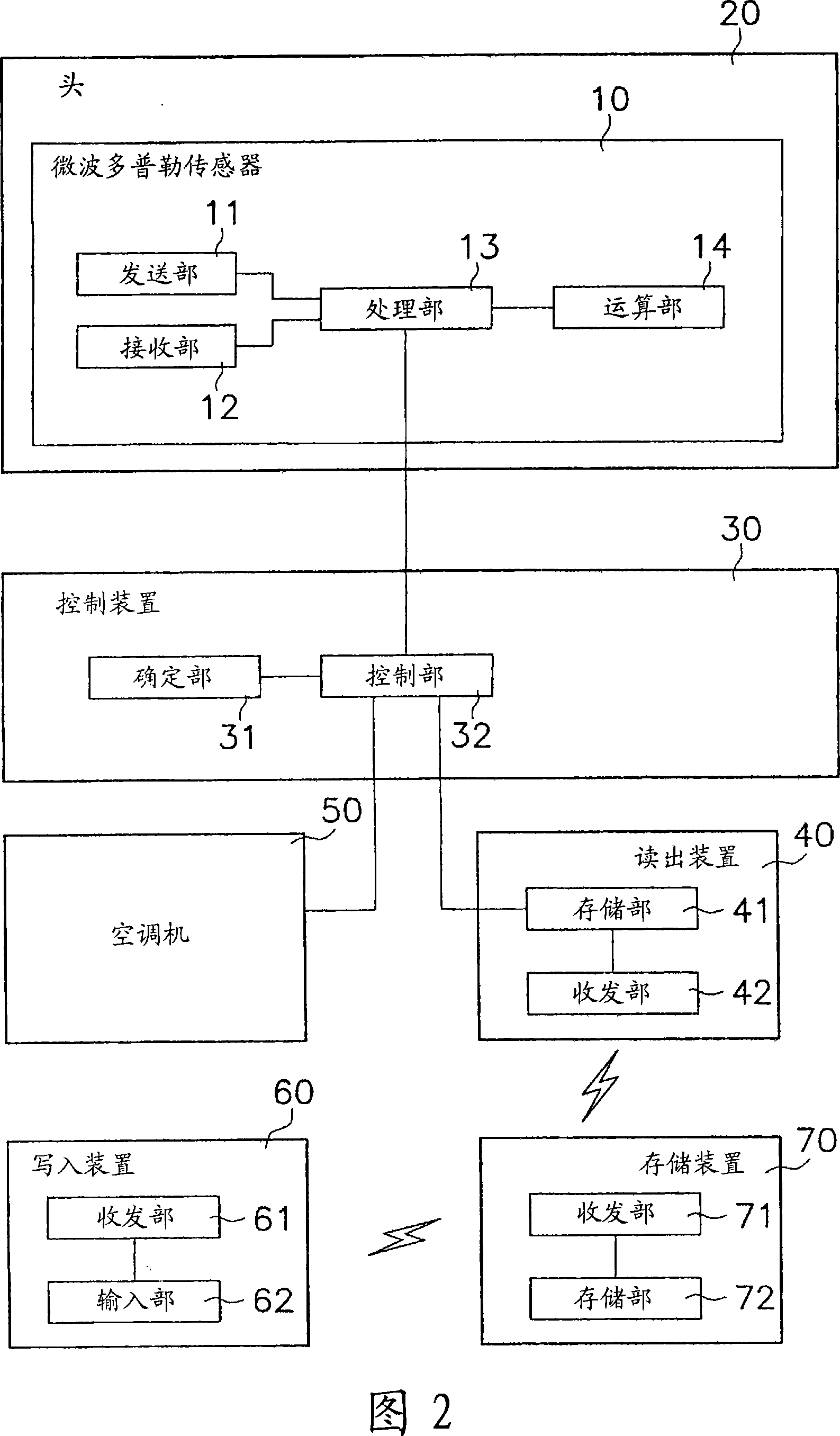
[0081] FIG. 1 shows a conceptual diagram of a sleep state improvement system 1 according to a first embodiment of the present invention. In addition, FIG. 2 shows a configuration diagram of components of the sleep state improvement system 1 according to the first embodiment of the present invention. The sleep state improvement system 1 shown in FIG. 1 is mainly a system for improving the sleep state of the user P. As shown in FIG.

[0082]

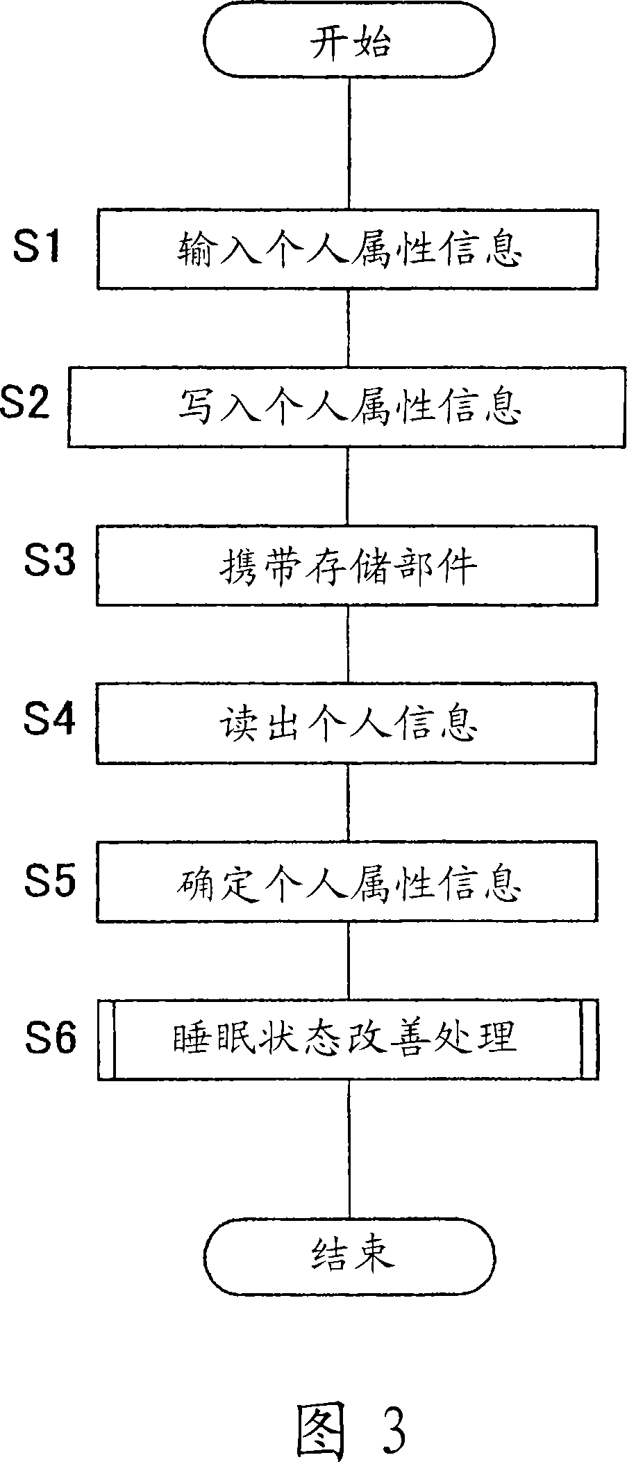
[0083] As shown in FIG. 1 , this sleep state improvement system 1 mainly includes a bed 20 , a control device 30 , a readout device 40 , an air conditioner 50 , a write device 60 and a storage unit 70 . The upper surface of the bed 20 is a place where the user P sleeps. The bed 20, the control device 30, the reading device 40, and the air conditioner 50 are provided in the room of the place where the user P (see FIG. 1) goes out. The storage unit 70 is brought by the user P (refer to FIG. 1 ) to the room at the place where the user goe...

no. 2 approach —

[0179] FIG. 9 shows a conceptual diagram of a sleep state improvement system 100 according to a second embodiment of the present invention. In addition, FIG. 10 shows a configuration diagram of each component of a sleep state improvement system 100 according to the second embodiment of the present invention. In FIGS. 9 and 10 , the same components as those of the sleep state improvement system 1 in FIGS. 1 and 2 are denoted by the same reference numerals. The sleep state improvement system 100 shown in FIG. 9 is mainly a system for improving the sleep state of the user P. As shown in FIG.

[0180] As shown in Fig. 9 and Fig. 10, although the basic structure of this sleep state improvement system 100 is the same as that of the first embodiment, and each component is the same as that of Fig. 2, it also has a management center 180 shown in Fig. 9, which is different from the first embodiment. The implementation is different. That is, the management center 180 , the reading devi...


PUM


Abstract

A sleeping state improvement system and a sleeping state improvement method capable of improving a sleeping state of a user even when the user sleeps away from home are provided. A sleeping state improvement system (1) is a sleeping state improvement system to improve a sleeping state of a user (P), comprising a memory member (70) and a control device (30) that comprises a specification unit (31) and a control unit (32). The memory member (70) can be carried by the user (P). The specification unit (31) specifies individual attribute information of the user (P) based on individual information. The individual information is information stored in the memory member (70). The control unit (32) controls an environment during sleep of the user (P) based on the individual attribute information.

Description

technical field [0001] The invention relates to a sleep state improving system and a sleep state improving method. Background technique [0002] Conventionally, a system for controlling an air conditioner or the like by estimating a sleep stage of a user has been proposed (see Patent Document 1). [0003] Patent Document 1: Japanese Patent Laid-Open No. 2003-339674 (pages 1 to 11, figures 1 to 19). [0004] However, in the prior art, there is a tendency that it is difficult to improve the sleep state of the user when the user goes out. That is, in the prior art, in order to improve the sleep state of the user, it is necessary to have a device for estimating the sleep stage, but because the device for estimating the sleep stage is bulky and heavy, it is difficult to carry it. For this reason, when the user goes out, the device for estimating the sleep stage cannot be used, and there is a tendency that the user's sleep state is difficult to improve when the user goes out. ...

Claims


Application Information

Patent Timeline
IPC IPC(8): A61M21/02A61B5/16A61B5/11F24F11/02G16H40/63
CPCG06F19/3481A61M2205/3606A61B5/4806A61M21/00A61B5/0507A61B5/4809A61M2205/52A61B5/1118A61M2021/0066A61M2205/6018G16H40/63
Inventor 新井润一郎三浦克哉石渡贵之田中正浩
Owner DAIKIN IND LTD
Learn More