Two rotation decoupling parallel robot mechanism

A robot and parallel technology, applied in manipulators, program-controlled manipulators, manufacturing tools, etc., can solve problems such as large cumulative errors, poor processing and assembly, and many branch motion pairs

Inactive Publication Date: 2007-10-24
YANSHAN UNIV
View PDF0 Cites 42 Cited by
  • Summary
  • Abstract
  • Description
  • Claims
  • Application Information

AI Technical Summary

Problems solved by technology

France's GOGU synthesized a type of two-degree-of-freedom decoupling parallel robot mechanism. This type of mechanism has only two branches, so it is not as good as the three branches in terms of stiffne...

Method used


Image

  • Two rotation decoupling parallel robot mechanism
  • Two rotation decoupling parallel robot mechanism
  • Two rotation decoupling parallel robot mechanism

Examples


Embodiment 1

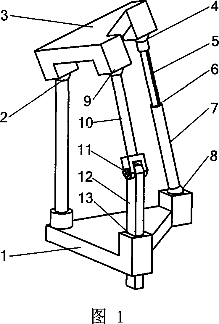
[0016] The moving platform 3 of this mechanism is connected with the fixed platform 1 through 3 branches (see Figure 1). There is only one ball pair 2 in the first branch. The ball pair 9 of the second branch connects the moving platform 3 and the connecting rod 10 , the rotating pair 11 connects the connecting rod 10 and the connecting rod 12 , and the connecting rod 12 is connected with the fixed platform 1 through the moving pair 13 . The first branch and the second branch form a planar guide rod mechanism. The ball pair 4 of the third branch connects the moving platform 3 and the connecting rod 5 , the moving pair 6 connects the connecting rod 5 and the connecting rod 7 , and the connecting rod 7 is connected with the fixed platform 1 through the ball pair 8 .

Embodiment 2

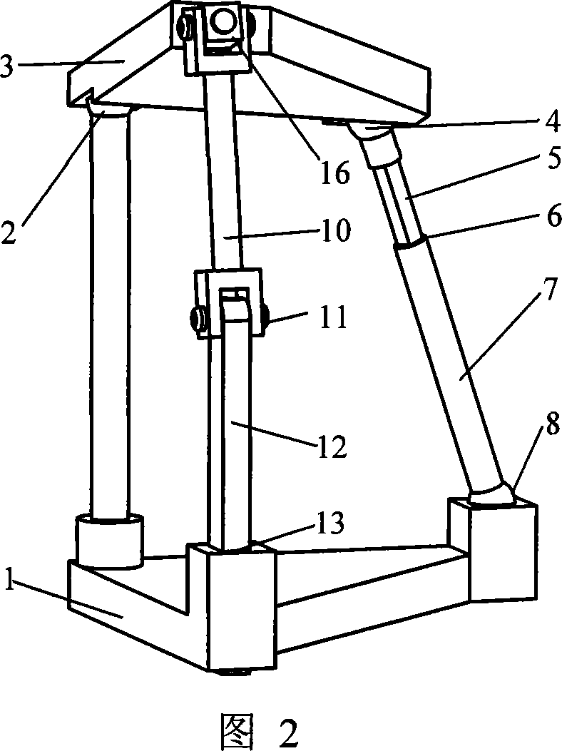
[0018] The moving platform 3 of this mechanism is connected with the fixed platform 1 through 3 branches (see Figure 2). There is only one ball pair 2 in the first branch. The Hooke hinge 16 of the second branch connects the moving platform 3 and the connecting rod 10, the rotating pair 11 connects the connecting rod 10 and the connecting rod 12, and the connecting rod 12 is connected with the fixed platform 1 through the moving pair 13, wherein one of the Hooke hinge 16 The axis passes through the center of the ball pair 2, and the other axis of the Hooke hinge 16 is parallel to the axis of the rotating pair 11. The first branch and the second branch form a planar guide rod mechanism. The ball pair 4 of the third branch connects the moving platform 3 and the connecting rod 5 , the moving pair 6 connects the connecting rod 5 and the connecting rod 7 , and the connecting rod 7 is connected with the fixed platform 1 through the ball pair 8 .

Embodiment 3

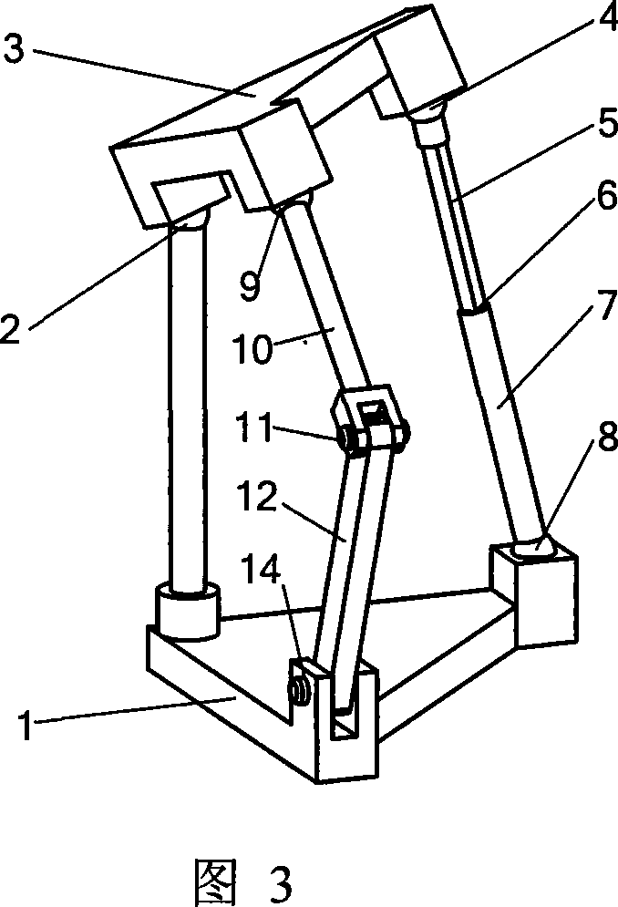
[0020] The moving platform 3 of this mechanism is connected with the fixed platform 1 through 3 branches (see Figure 3). There is only one ball pair 2 in the first branch. The ball pair 9 of the second branch connects the moving platform 3 and the connecting rod 10, and the rotating pair 11 connects the connecting rod 10 and the connecting rod 12, and the connecting rod 12 is connected with the fixed platform 1 through the rotating pair 14, wherein the axis of the rotating pair 14 is connected with the rotating The axes of the vice 11 are parallel. The first branch and the second branch constitute a planar hinge mechanism. The ball pair 4 of the third branch connects the moving platform 3 and the connecting rod 5 , the moving pair 6 connects the connecting rod 5 and the connecting rod 7 , and the connecting rod 7 is connected with the fixed platform 1 through the ball pair 8 .


PUM


Abstract

The invention relates to parallel robot industry, comprising dynamic and static platforms and three branches connected to them. I features in the dynamic platform through three branches and connected to the static platform, with one branch having a movement sub, the second branch having three movement subs, the first and the second branches forming into horizontal guide pole structure or plane hinge structure, with the third branch having space for six freedom branch chains. It enjoys high rigidity, simple structure, two rotary complete decoupling, easy for control, low in movement quality, good in dynamic features.

Description

technical field [0001] The invention belongs to the field of parallel robots, in particular to a group of two rotational degrees of freedom motion decoupling parallel robot mechanisms. Background technique [0002] The parallel robot mechanism has multiple degrees of freedom and multi-loop closed chain in space. Compared with the series mechanism, the parallel mechanism has the characteristics of high rigidity, large bearing capacity, small cumulative error, good dynamic characteristics, and compact structure. At present, parallel mechanisms are widely used in virtual axis machine tools, micro-motion consoles, various motion simulators, sensors, etc. [0003] Compared with the serial robot mechanism, the parallel robot mechanism has the disadvantages of small working space, strong coupling between motions, and difficult control. At present, the decoupled parallel robot mechanisms synthesized in the world mainly include three-movement-degree-of-freedom and three-movement-one...

Claims


Application Information

Patent Timeline
IPC IPC(8): B25J19/00B25J9/08
Inventor 黄真曾达幸卢文娟
Owner YANSHAN UNIV
Why Eureka
Try Eureka