
A building element and a building structure comprising the building element

A technology of building components and building structures, which is applied in building components, building structures, buildings, etc., and can solve problems such as moisture

Inactive Publication Date: 2007-10-31
罗杰·埃里克松
View PDF2 Cites 0 Cited by
  • Summary
  • Abstract
  • Description
  • Claims
  • Application Information

AI Technical Summary

Problems solved by technology

Moisture issues occur due to the large amount of water and it takes a considerable amount of time to dry these additional layers

Method used


Image

  • A building element and a building structure comprising the building element
  • A building element and a building structure comprising the building element
  • A building element and a building structure comprising the building element

Examples


Embodiment Construction

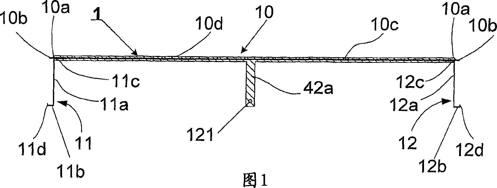
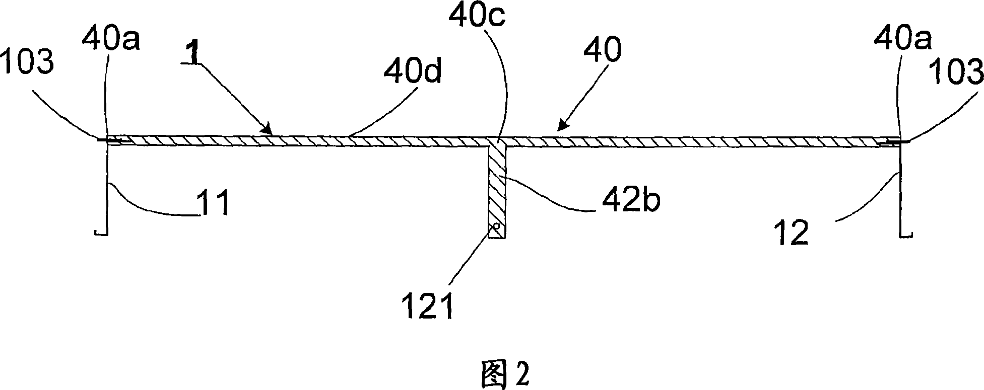
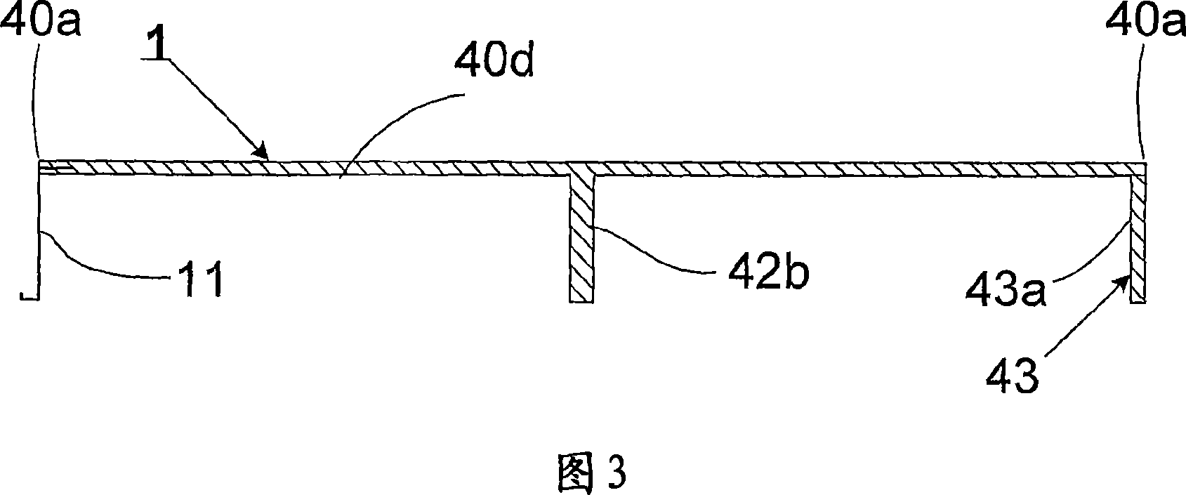
[0044] Figure 1 shows a building element 1 according to one embodiment of the invention. The building element 1 can have many alternative shapes, but in this embodiment it is elongated and one of the short sides of the building element can be seen from FIG. 1 .

[0045] The building element 1 comprises: a component 10 having a planar portion 1Od, which in this embodiment is in the form of a rectangular upper plate portion 1Od; and an intermediate beam portion 42a protruding from a central area of ​​the planar portion 1Od. The component 10 preferably comprises high performance concrete, preferably reinforced high performance concrete of the type described in PCT / SE2004 / 000148, which is hereby incorporated by reference. The beam portion 42a preferably has an I-shaped cross-section extending laterally substantially perpendicular to the planar portion 10d. Alternatively, part 10 may comprise more than one beam, preferably each beam has substantially the same configuration, ie ext...


PUM


Abstract

The invention relates to a building element for a building structure such as a floor structure, comprising a member (10, 21, 40), said member having a planar portion (10d, 40d), and at least a part (11, 12, 43, 44, 45) of a mould (111) provided at an edge (10a, 21a, 40a) of the member (10, 21, 40).

Description

technical field [0001] The invention relates to a building element for building structures such as floor structures according to the preamble of claim 1 . Background technique [0002] In known building construction procedures, such as those involving multi-storey buildings, the floor structure is usually fabricated on site and cast as a homogeneous reinforced concrete structure with acceptable sound dampening and fire protection properties. However, this conventional method of construction requires a relatively large amount of man-hours on the job site, which increases construction time and / or the number of workers required. [0003] There are many methods for increasing the degree of prefabrication. A fully prefabricated floor structure was not feasible due to issues such as being very heavy to carry and the inability to meet tolerances requiring additional cast-in-place. Many prefabrication methods involve making the lower roof of the concrete floor structure, with or w...

Claims


Application Information

Patent Timeline
Patent Type & Authority Applications(China)
IPC IPC(8): E04B5/02E04B5/18E04B5/17E04B5/23E04B
CPCE04B5/046E04B5/04
Inventor 罗杰·埃里克松
Owner 罗杰·埃里克松
Learn More