Centrifugal guide vane

A guide vane and blade technology, applied in the direction of the swirl axis can be reversed, the swirl device, etc., can solve the problems of large resistance loss, high amount of fine dust in the air, and inability to separate fine dust particles, etc. The effect of ensuring the urgency of the end, increasing the entry area, and prolonging the time

Active Publication Date: 2010-05-19
JIANGSU XINHUANENG ENVIRONMENTAL ENG CO LTD
View PDF12 Cites 0 Cited by
  • Summary
  • Abstract
  • Description
  • Claims
  • Application Information

AI Technical Summary

Problems solved by technology

[0006] After further exploration by the applicant, it was found that the above-mentioned centrifugal guide vanes have advantages and disadvantages, that is, because the angle at which the dust-laden air enters the swirl cylinder is single, the passage area of ​​the dust-laden air passing through the centrifugal guide vanes is small, and the resistance loss is large, thereby reducing The rotation strength of the dust-laden air in the cyclone cylinder cannot make the fine dust particles be separated from the flue gas by sufficient separation force in the cyclone airflow, that is, it is difficult to make the fine dust particles settle in the cyclone cylinder and enter the conical ash filter. bucket, resulting in a high amount of fine dust in the purified air, so the dust removal efficiency is still not enough to achieve the ideal level that people expect

Method used


Image

  • Centrifugal guide vane
  • Centrifugal guide vane
  • Centrifugal guide vane

Examples


Embodiment Construction

[0015] In order to enable the examiners of the patent office, especially the public, to further understand the essence and beneficial effects of the present invention, the applicant describes in detail the following specific examples, but the examples cannot be regarded as constituting limitations to the structure of the present invention.

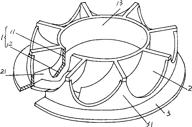
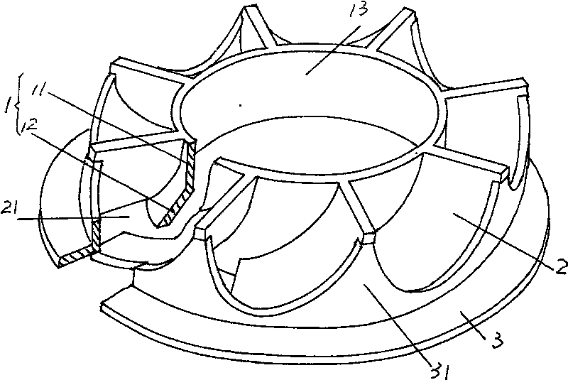
[0016] see figure 1 , as the body 1 of the centrifugal guide vane, the upper part is designed as a straight cylinder 11, and the lower part forms an outwardly expanded horn body 12, and the outer wall of the body 1 is formed as a paraboloid by the straight cylinder 11 and the horn body 12. It also helps to improve (change) the entry angle or cutting angle of the dusty air entering the cyclone cylinder. Between the outer wall of the main body 1, that is, the outer wall formed by the straight pipe body 11 and the trumpet body 12, a group of blades 2 with a shape tending to be tile-shaped is arranged. The recommended number of blades in this ...


PUM


Abstract

The invention is concerned with a kind of radial guide vane, belonging to environment friendly establishment technology field to remove smoke and gas. It has a body which having a vertical tube as upper part and a bugle shape as lower part and a group of vane that setting on the ektexine of body. There is a connecting loop outside of the body and it extends to form projecting edge as skirt borderand the edge connects with vane. Because of the connecting loop, so when the gas with dust passing through the channel among the vanes, the enter angle of gas will change by the wall of projecting edge and change into solid enter from plane of vane's surface. This increases the enter area and avoids gas with dust escaping form the lower side of vane and keep the state of gas with dust into the revolving canister, prolong the rotating time in the revolving canister to keep more dust falling to taper ash gather filler.

Description

technical field [0001] The invention relates to a centrifugal guide vane, which is used in cyclone separation and dust removal equipment for dust removal of flue gas in iron and steel enterprises such as pelletizing plants, coking plants, and sintering plants, and belongs to the technical field of environmental protection facilities for dust removal of flue gas. Background technique [0002] Since the centrifugal guide vane and the swirl cylinder are usually referred to as the guide and the cyclone respectively, the centrifuge composed of the centrifugal guide vane and the swirl cylinder is also usually called a cyclone. Regarding the centrifuge, it can be seen from Chinese patent ZL98226235.3, which is based on the centrifugal guide vane ( Patent called guide) and centrifugal conduit (also known as inner cylinder) are made as a whole, which causes inconvenience to the maintenance and repair of the swirl cylinder and the cleaning of dust, so it is conceived to separate the c...

Claims


Application Information

Patent Timeline
Patent Type & Authority Patents(China)
IPC IPC(8): B04C5/103B04C5/107
Inventor 赵克宇
Owner JIANGSU XINHUANENG ENVIRONMENTAL ENG CO LTD
Why Eureka
Try Eureka