Data Center Air Routing System

a data center and air routing technology, applied in the direction of cooling/ventilation/heating modifications, electrical apparatus casings/cabinets/drawers, electrical apparatus, etc., can solve the problems of affecting the performance and efficiency affecting the cooling needs of new racks, and affecting the performance of the original cooling infrastructure. to achieve the effect of inhibiting unwanted air from infiltrating and preventing unwanted air from entering or escaping the interior

Active Publication Date: 2010-06-10
EATON INTELLIGENT POWER LIMITED
View PDF11 Cites 165 Cited by
  • Summary
  • Abstract
  • Description
  • Claims
  • Application Information

AI Technical Summary

Benefits of technology

[0034]In an embodiment, the data center air routing system of the invention comprises a free-standing structure comprising a frame that defines the edges of two sidewalls, a ceiling and two ends that together define an interior aisle, where the sidewalls comprise a plurality of full-height sidewall blanking panels that are removably coupled at their upper and lower ends to the frame and are releasably coupled to each other, so as to allow one or more IT racks to be coupled to either side of the structure, to route air between the structure and the IT racks; one or more top panels sized and shaped to fill the space between the tops of the one or more IT racks and the top edge of the frame; where the structure is relatively air-tight, to prevent unwanted air from infiltrating or escaping the interior of the structure; and a door located at one or both ends, to allow personnel access to the interior aisle, and inhibit unwanted air flow.

Problems solved by technology

Companies that house data center rooms are faced with difficult challenges in providing the proper thermal environment for information technology (IT) equipment.
Compounding the problem, when data centers add new and different equipment the performance and efficiency of the original cooling infrastructure is impacted.
New racks may not fit in the same footprint or have the same cooling needs.
Implementing these moves, additions and changes is therefore difficult without a flexible system designed to meet these challenges.
The increasing demand, and strain, placed upon electrical grids across the United States by data centers of all sizes is a material contributor to this issue.
There has been little incentive, however, for data center managers to optimize the energy efficiency of their data center.
In addition, the industry has not set any proper benchmarks for attainable energy efficiency targets, which further complicates the situation.
Data center managers are primarily concerned about capital costs related to their data center's capacity and reliability.
(1) An open air system that delivers cold air at approximately 55 degrees Fahrenheit (approximately 13 degrees Celsius) via overhead ducting, flooded room supply air, or a raised floor plenum;
(2) Perforated tiles (in a raised floor environment) that are used to channel the cold air from beneath the raised floor plenum into the data center;
(3) Computer racks, server enclosures and free-standing equipment orientated 180 degrees from alternate rows to create hot and cold aisles, which is an accepted best practice. Historically, however, information technology (IT) architecture has been the driving force in deciding the location of the racks and other equipment, leading to a disorganized and inefficient approach to air distribution;
(4) Computer racks, server enclosures and free-standing equipment that vary in size and shape;
(5) A minimum separation of 4 feet (approximately 1.22 meters) between cold aisles and 3 feet (approximately 0.91 meters) between hot aisles, based on recommendations from the American National Standards Institute (ANSI / TIA / EIA-942 April 2005), National Fire Protection Association (NFPA), National Electric Code (NEC), and local Authority Having Jurisdiction (AHJ);
(6) Dedicated precision air conditioning units located at the nearest perimeter wall and generally in close proximity to IT racks. However, optimal placement of the computer room air conditioner (CRAC) for free air movement is biased by structural columns, and often requires service clearances or other infrastructure accommodations;
(7) Traditional air conditioning systems are “turned on” on day one, and remain at full capability for cooling, even if only a small percentage of the design load is required; and
(8) Existing air conditioning systems have limitations and are sensitive to the location of heat loads in and around the data center, and therefore are not resilient to changing configurations and requirements.
In practice, the airflow in the legacy data center is very unpredictable, and has numerous inefficiencies, which are proliferated as power densities increase.
Problems encountered in a data center include: bypass airflow, recirculation, hot and cold air remixing, air stratification, air stagnation, and uncomfortable data center ambient room temperature.
This amounts to a tremendous waste in energy, as well as an excessive and unnecessary operational expense.
Recirculation can result in potential overheating and damage to computing equipment, which may cause disruption to mission-critical services in the data center.
Thus, in a legacy data center design, the computer room is overcooled by sending extremely cold air under the raised floor, simply because there is a lack of temperature control as the air moves upward through the rack or cabinet enclosure.
In addition, because the hot air and the cold air are not isolated, and tend to mix, dedicated air conditioning units are typically located close to the rack enclosures, which may not be the most efficient or economical placement.
As a result, the available cooling cannot be delivered to the computing equipment.
Data center ambient room temperature is not conditioned to comfortable working conditions.
A particular in-row air conditioning unit, however, is constrained by its location, in that it may only be used to cool the equipment in the row in which it is located.
An in-row air conditioning unit's excess cooling capacity cannot be used to cool equipment racks in a different row.
In addition, an in-row air conditioning unit does nothing to reduce the temperature in the hot aisle, and in some cases, may actually increase the temperature in the hot aisle beyond recommended safety limits.

Method used


Image

  • Data Center Air Routing System
  • Data Center Air Routing System
  • Data Center Air Routing System

Examples


Embodiment Construction

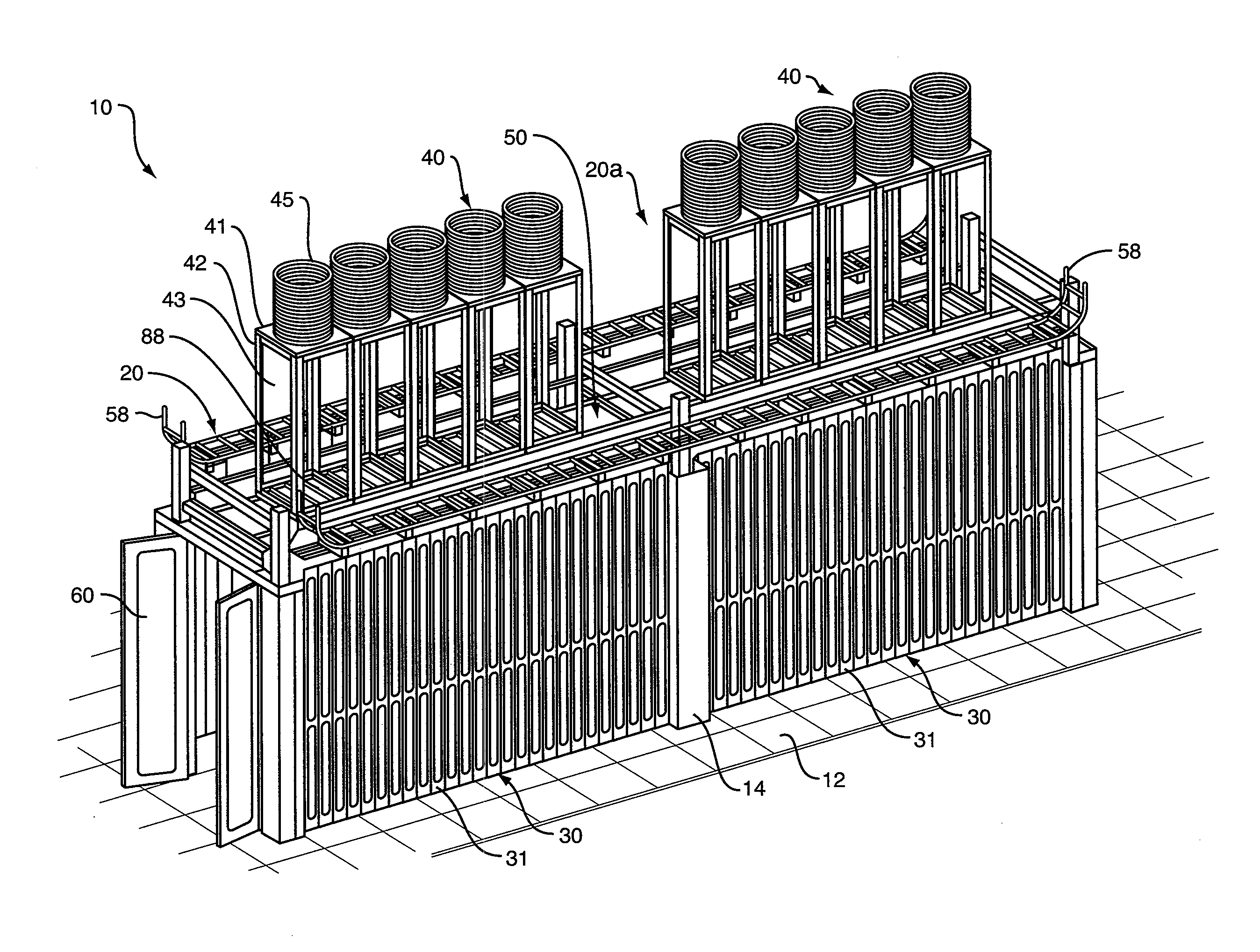
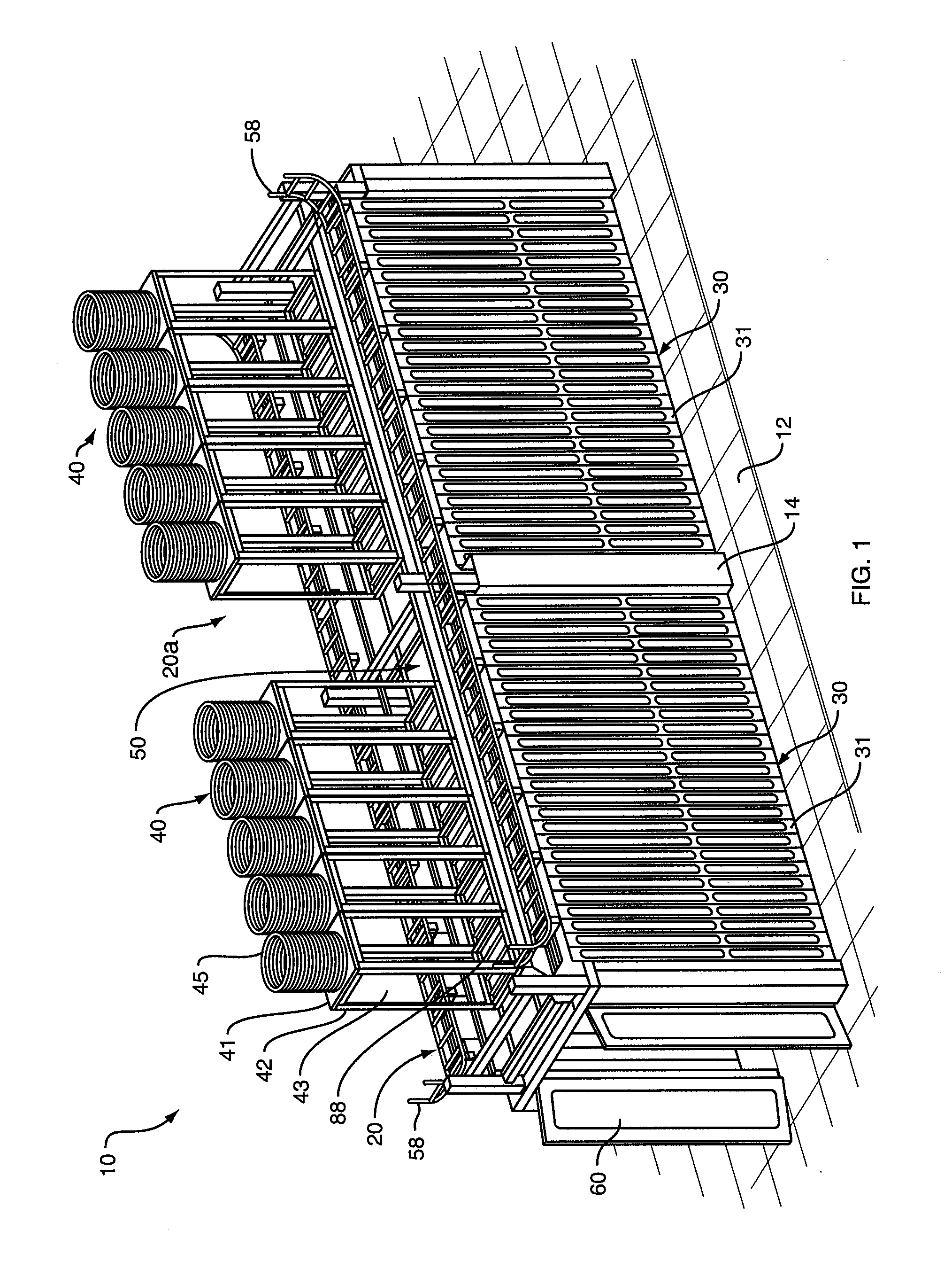
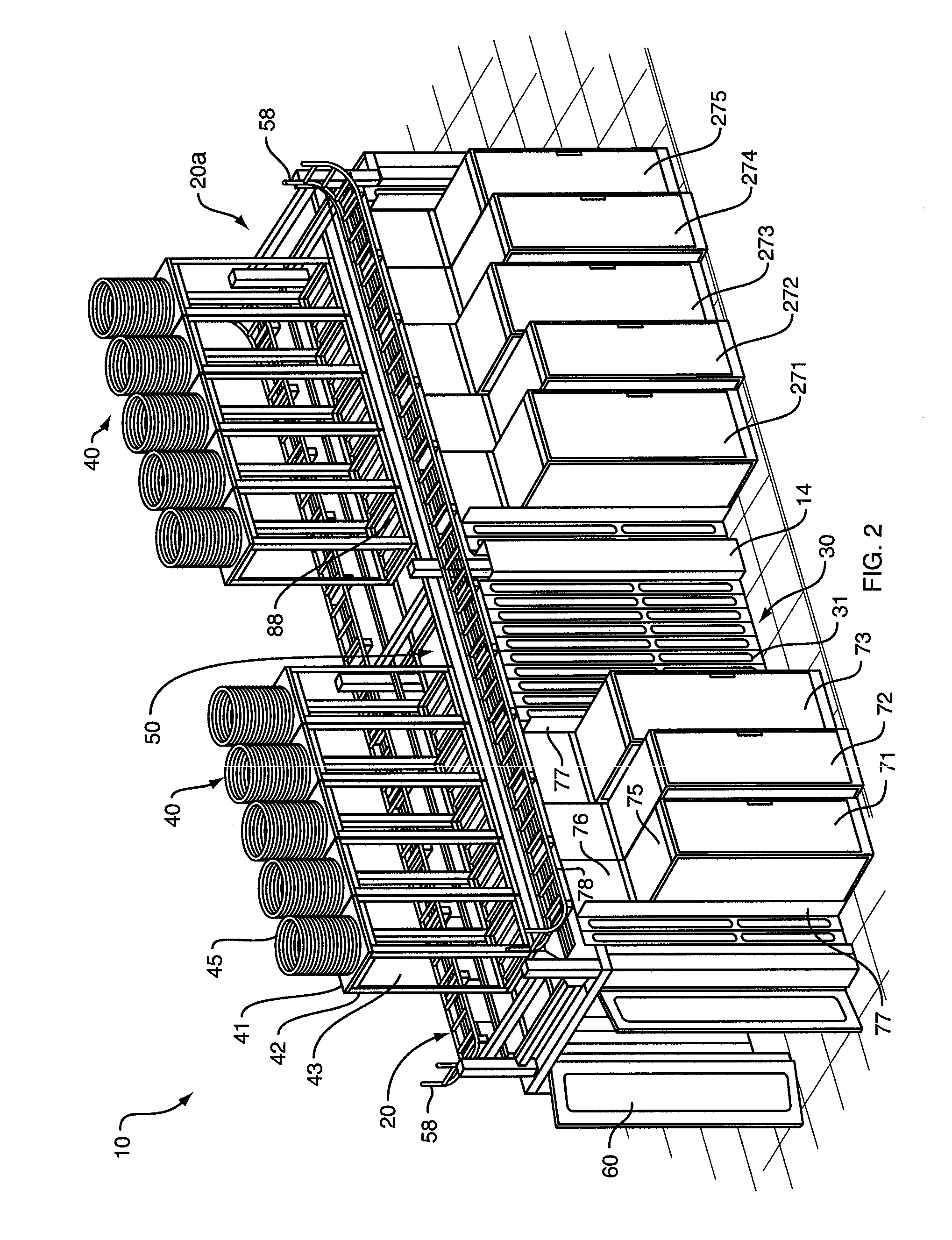
[0073]In a preferred embodiment, and as shown in FIGS. 1 and 2, data center air routing system 10 comprises two free-standing, essentially identical, modular system units 20 and 20a. Note that in alternate embodiments, the data center air routing system of the invention may comprise only one modular system unit, or may comprise more than two free-standing, essentially identical, modular system units, which may be coupled end-to-end.

[0074]With further reference to FIGS. 1 and 2, modular system units 20 and 20a are preferably coupled together by connector structure 14, described below. Each modular system unit 20 (and 20a) is a generally rectangular, free-standing structure comprising two essentially identical sidewalls, such as sidewall 30, a ceiling 50, and two doors 60, one at either end of the modular system unit, thus forming an interior, enclosed aisle. While modular system unit 20 may further comprise an optional floor, in a preferred embodiment the modular system unit is confi...


PUM


Abstract

The invention provides a modular, configurable aisle isolation and containment system that may function as a hot aisle or as a cold aisle. The data center air routing system of the invention comprises one or more free-standing, essentially identical, modular system units. Each modular unit comprises two sidewalls, a ceiling, and a door or panel at either end to form an interior, enclosed aisle. Two or modular units may be coupled together end-to-end. Each modular unit further comprises one or more sidewall blanking panels that may be removed to create gaps of varying height and width to accommodate one or more IT racks. Each modular unit may also include one or more ceiling-mounted air ducts, baffles and fans to manage air flow.

Description

CROSS-REFERENCE TO RELATED APPLICATIONS[0001]This application claims priority to U.S. Provisional Patent Application Ser. No. 61 / 108,066, entitled “Data Center Air Routing System,” filed on Oct. 24, 2008, the entire contents of which are expressly incorporated by reference herein.FIELD OF THE INVENTION[0002]The invention relates generally to the field of data center airflow and temperature management. Specifically, the invention combines elements of both heat containment and cold air isolation systems to create a modular, configurable aisle isolation and containment system that applies to either hot or cold aisles and also to the combination of both.BACKGROUND OF THE INVENTION[0003]Companies that house data center rooms are faced with difficult challenges in providing the proper thermal environment for information technology (IT) equipment. IT equipment must operate under specific temperature ranges and data center rooms must be able to accommodate those ranges. Providing the approp...

Claims


Application Information

Patent Timeline
Patent Type & Authority Applications(United States)
IPC IPC(8): H05K7/20
CPCH05K7/20745
Inventor BEDNARCIK, EDWARDTRESH, MICHAELJACKSON, BRIAN
Owner EATON INTELLIGENT POWER LIMITED
Why Eureka
Try Eureka