Clamping device

A clamping device and clamping arm technology, applied in workpiece clamping devices, metal processing, manufacturing tools, etc., can solve the problems of low lens yield and lens damage, and achieve the goal of avoiding lens damage and ensuring lens yield. Effect

Inactive Publication Date: 2007-12-05
HONG FU JIN PRECISION IND (SHENZHEN) CO LTD +1
View PDF0 Cites 4 Cited by
  • Summary
  • Abstract
  • Description
  • Claims
  • Application Information

AI Technical Summary

Problems solved by technology

However, for the molding element 30 formed by this kind of H-shaped runner, the distance between the plastic lens 321 and the plastic lens 322 and the runner head 36 is relatively short. When clamping the plastic lens 321 to be cut, the clamping The device is easy to collide with the plastic lens 322 or / and the runner head 36, resulting in damage to the lens, resulting in low yield of the lens

Method used


Image

  • Clamping device
  • Clamping device
  • Clamping device

Examples


Embodiment Construction

[0012] The embodiments of the present invention will be further described in detail below in conjunction with the accompanying drawings.

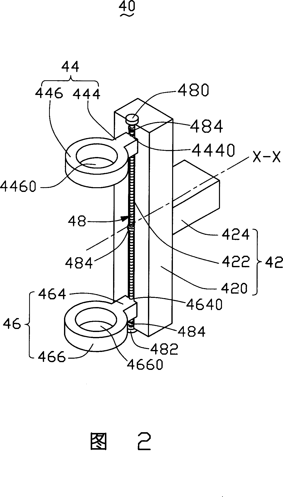
[0013] Referring to FIG. 2, the clamping device 40 provided by the embodiment of the present invention includes a supporting mechanism 42, clamping arms 44 and 46, and a driving mechanism 48.

[0014] The supporting mechanism 42 is used to support the clamping arms 44 and 46. The supporting mechanism 42 includes a main body 420, a sliding groove 422 and a supporting rod 424. The sliding groove 422 is provided on one side of the main body 420. The supporting rod 424 may be provided on the other side of the main body 420 opposite to the sliding groove 422. The supporting rod 424 and the main body 420 are integrated. When an external force acts on the supporting rod 424, the supporting rod 424 can drive the main body 420 rotates around the central axis XX of the support rod 424 together. The support rod 424 can be a prism, a cylinder, etc., and ca...


PUM


Abstract

The present invention is one holding device for holding one cut plastic lens including one optical area and one structural area around the optical area. The holding device includes two holding arms and one driving mechanism connected to the holding arms for mutual approach or separation. Each of the holding arms includes one holding mechanism and one holding part for holding the optical area of the held plastic lens. The holding device holds the plastic lens to be cut in the optical axis direction of the lens, and can avoid collision damage of the lens and raise the high quality of the lens.

Description

Technical field [0001] The invention relates to a clamping device, in particular to a clamping device for clamping a lens to be cut. Background technique [0002] At present, plastic lenses are widely used in consumer electronic products such as digital cameras and camera phones due to their low cost. Generally, plastic lenses are made by injection molding. Figure 1 shows a schematic diagram of a plastic lens molded with an H-shaped runner. The molding element 30 formed by the H-shaped runner includes eight plastic lenses 321, 322, 323, 324, 325, 326, 327, and 328 that are formed at one time. The eight plastic lenses pass through the runner material head 36 and the runner material head. 34 connected together. Before cutting the molding element 30, a clamping device needs to be used to clamp the plastic lens to be cut. However, for this kind of H-shaped runner molding molding element 30, the distance between the plastic lens 321 and the plastic lens 322 and the runner head 36 is r...

Claims


Application Information

Patent Timeline
IPC IPC(8): B26D7/01B25B11/00
Inventor 李欣和
Owner HONG FU JIN PRECISION IND (SHENZHEN) CO LTD
Why Eureka
Try Eureka