Supercharge Your Innovation With Domain-Expert AI Agents!

Horizontal plastic injection forming machine injection head

An injection molding machine and injection head technology, applied in the field of injection nozzles and injection heads, can solve the problems of fluid material leakage, material leakage, poor sealing performance at the feeding port, etc., and achieve the effect of preventing leakage

Inactive Publication Date: 2010-12-22
金孝禹
View PDF0 Cites 0 Cited by
  • Summary
  • Abstract
  • Description
  • Claims
  • Application Information

AI Technical Summary

Problems solved by technology

[0005] The feed port of the traditional injection head is directly connected to the discharge port of the horizontal pre-molding mechanism. The disadvantage is that the sealing performance of the connection surface, that is, the feed port, is not good, and material leakage is prone to occur.
In addition, the plasticized fluid material is easy to leak from the injection port, which brings unnecessary economic losses to the owner.

Method used


Image

  • Horizontal plastic injection forming machine injection head
  • Horizontal plastic injection forming machine injection head
  • Horizontal plastic injection forming machine injection head

Examples


Embodiment 1

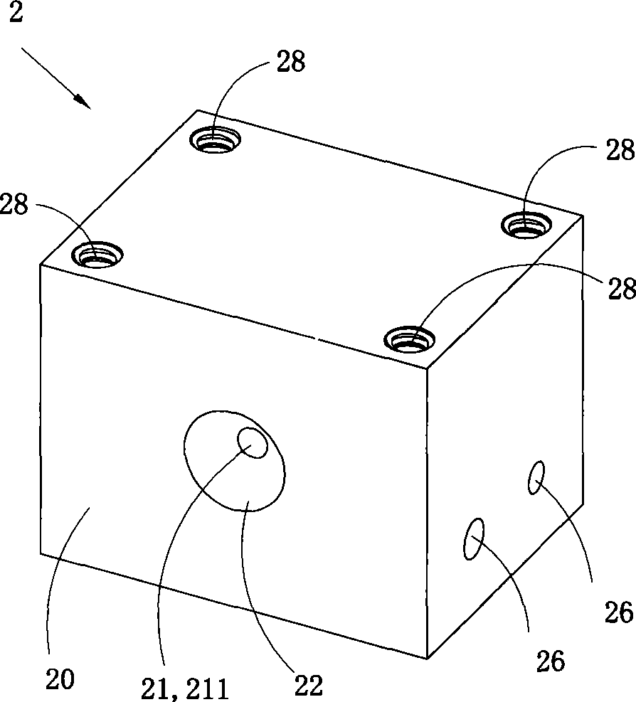
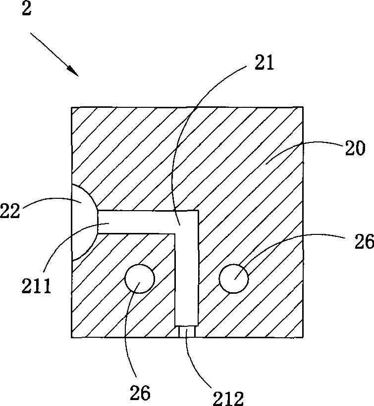
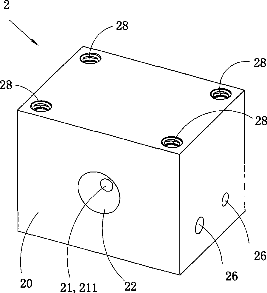
[0052] Figure 1 to Figure 2 A first embodiment of the invention is shown in which, figure 1 It is a three-dimensional structural schematic diagram of the first structure of the present invention. figure 2 yes figure 1 half cutaway view.

[0053] This embodiment is an injection head 2 used for a horizontal plastic injection molding machine, and its body 20 is provided with an injection channel 21, and the injection channel 21 has a material inlet 211 and a material injection port 212; the injection The head body 20 is provided with a feed connection part 22 at the feed port 211, the basic shape of the feed connection part 22 is a hemispherical groove with a concave spherical surface or a conical groove with a concave conical surface, The feed opening 211 is located at the center of the feed connection part 22 .

[0054] See figure 1 , The front of the injection head body 20 is provided with two through holes 26, and the through holes 26 are used for inserting an electric...

Embodiment 2

[0058] Figure 3 to Figure 7 A second embodiment of the invention is shown in which, image 3 It is a three-dimensional structural schematic diagram of the second structure of the present invention. Figure 4 yes image 3 A schematic diagram of the three-dimensional structure of the injection head shown when viewed from another angle. Figure 5 yes image 3 Half-cut view of the injection head shown. Image 6 yes Figure 5 The partially enlarged schematic diagram at middle F. Figure 7 yes image 3 A half-section view of the injection nozzle in the injection head shown.

[0059] This embodiment is basically the same as Embodiment 1, the difference is: see Figure 3 to Figure 7 , the injection nozzle 1 that can inject material and prevent material leakage is inserted in the injection port 212 of the injection channel 21. The basic shape of the injection nozzle 1 is a T-shape with a large top and a small bottom, the upper part is a sealing part 11, and the lower part is ...

Embodiment approach

[0061] Figure 8 to Figure 17 A third embodiment of the invention is shown, in which Figure 8 It is a schematic diagram of the three-dimensional structure of the third structure of the present invention. Figure 9 yes Figure 8 The schematic diagram of the three-dimensional structure of the injection head when viewed from another angle. Figure 10 yes Figure 8 The schematic diagram of the three-dimensional structure of the injection head body in the injection head shown. Figure 11 yes Figure 10 Front view of the injection tip body shown. Figure 12 yes Figure 11 B direction view. Figure 13 yes Figure 12 C-C cross-sectional view of . Figure 14 yes Figure 12 D-D cross-sectional view of . Figure 15 is Figure 9 The schematic diagram of the three-dimensional structure of the injection coupler in the injection head shown. Figure 16 yes Figure 9 Half-cut view of the injection head shown. Figure 17 is adopted Figure 9 A plastic injection molding machine m...


PUM


Abstract

The invention discloses an injection head for a horizontal plastic injection molding machine. The body of the injection head is provided with a feeding pore canal which is provided with a feeding port and an injection port; the body of the injection head is provided with a feeding connection part at the feeding port; the feeding connection part basically takes the shape of a semi-sphere groove with a concave sphere or a conical groove with a concave conical surface; the feeding port is arranged at the center of the feeding connection part at the feeding port. With good sealing function, the invention can prevent the leakage of the materials, thus the invention is widely applicable.

Description

technical field [0001] The invention belongs to the field of plastic injection molding machinery design, in particular to an injection nozzle and an injection head using the injection nozzle. Background technique [0002] Disc-type plastic injection molding machine is a kind of equipment specially used for manufacturing plastic soles. The discs used are often equipped with multiple sole molds of the same style and different sizes at the same time. Therefore, it is necessary to set the molds on the turntable for plastic The injection molding machine injects and molds molds with the same style and different code numbers in stages, and facilitates the process of opening the mold and taking out the molded sole. [0003] Disc plastic injection molding machines are generally divided into horizontal plastic injection molding machines and vertical plastic injection molding machines due to the different selection of pre-molding mechanisms. Horizontal plastic injection molding machine...

Claims


Application Information

Patent Timeline
Patent Type & Authority Patents(China)
IPC IPC(8): B29C45/20B29C45/23B29C45/74B29C45/17
Inventor 金孝禹
Owner 金孝禹
Features
  • R&D
  • Intellectual Property
  • Life Sciences
  • Materials
  • Tech Scout
  • Unparalleled Data Quality
  • Higher Quality Content
  • 60% Fewer Hallucinations
Learn More