Link failure diagnosis device of hand-hold passive optical network

A passive optical network, link failure technology, applied in the multiplexing system selection device, selection device, data exchange network and other directions, can solve the problem of no portable PON link monitoring device, etc., to achieve intuitive display and operation. Simple and flexible effects

Inactive Publication Date: 2008-01-30
沈成彬 +1
View PDF0 Cites 54 Cited by
  • Summary
  • Abstract
  • Description
  • Claims
  • Application Information

AI Technical Summary

Benefits of technology

This patented technology helps detect problems such as optical fibers being cut off due to environmental factors like temperature changes over time. It uses specialized components called support records for testing these conditions during normal use. These tests help identify any issues early on before they become critical because it provides valuable insights into how well your networks work properly.

Problems solved by technology

This patents describes how physical connections between different components like routers and servers may fail overtime due to factors like temperature changes and agitation caused by winds. To diagnose these issues, physicists often utilized special tools called Power Meters (PEM' s abbreviation from Electrical Meter Company Limited) to capture signals on their own wires. However, current methods require manual intervention during troubleshooting operations, making them difficult to implement continuously without interrupting normal communication sessions. Additionally, they lack flexibility when performing various analyzes needed.

Method used


Image

  • Link failure diagnosis device of hand-hold passive optical network
  • Link failure diagnosis device of hand-hold passive optical network
  • Link failure diagnosis device of hand-hold passive optical network

Examples


Embodiment Construction

[0047] The specific implementation manners of the present invention will be described in detail below with reference to the accompanying drawings.

[0048] Aiming at the problem that there is no portable PON link fault diagnosis device at present, the present invention provides a hand-held device for PON network link state monitoring and fault diagnosis.

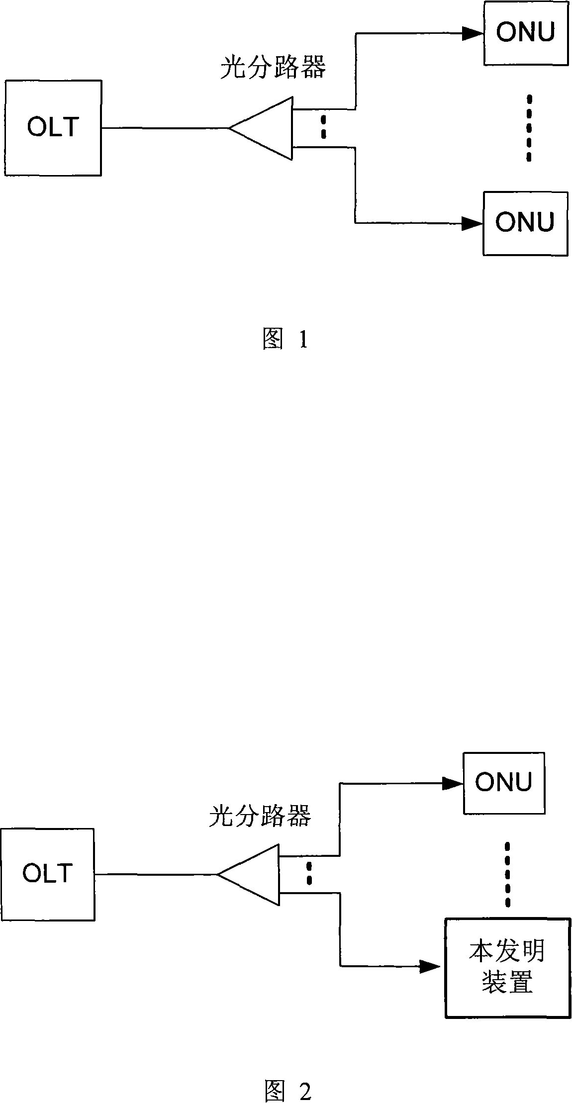
[0049] Fig. 1 introduces the PON network topology related to the device of the present invention. It can be seen from the figure that an OLTPON port can be connected to multiple ONUs through an optical splitter. The downlink data transmission method from the OLT to the ONU is a time-division multiplexed physical layer broadcast method, that is, each downlink frame will be sent to the PON ports of all ONUs. The uplink data transmission mode from ONU to OLT is TDMA (for EPON and GPON), that is, each ONU sends uplink data in the uplink time slot allocated by OLT for its own use.

[0050] Fig. 2 has introduced the typical appl...


PUM


Abstract

The invention relates to a failure diagnostic device for a passive optical network (PON) link, which comprises the following parts: an optical signal processing subsystem, a PON subsystem, a processor (CPU) subsystem, a user interface (I/O) subsystem, a business interface subsystem, a clock subsystem and a power subsystem. The primary function of the device comprises the physical layer testing, link layer testing, business layer testing of the PON interface and the display, record and preservation of the testing results. The device of the invention has distinct characteristics and advantages that: firstly, the device can make overall monitoring to the link situation of the PON system and all kinds of key parameters and can clearly position every failure of the PON system; secondly, the device is a handheld device with simple and flexible operation, which is suitable for the installation of the PON network equipments, project acceptance and maintenance applications; thirdly, a modularized structure can provide different testing functions by adding the VoIP business modules and IPTV business modules.

Description


Claims


Application Information

Patent Timeline
Owner 沈成彬
Why Eureka
Try Eureka