
Dose uniformity during scanned ion implantation

An ion implantation and ion beam technology, applied in the field of semiconductor processing systems, can solve the problem of large size of the ion implanter

Inactive Publication Date: 2008-02-13
AXCELIS TECHNOLOGIES
View PDF0 Cites 7 Cited by
  • Summary
  • Abstract
  • Description
  • Claims
  • Application Information

AI Technical Summary

Problems solved by technology

However, processing substrates in such batches typically makes ion implanters considerably larger

Method used


Image

  • Dose uniformity during scanned ion implantation
  • Dose uniformity during scanned ion implantation
  • Dose uniformity during scanned ion implantation

Examples


Embodiment Construction

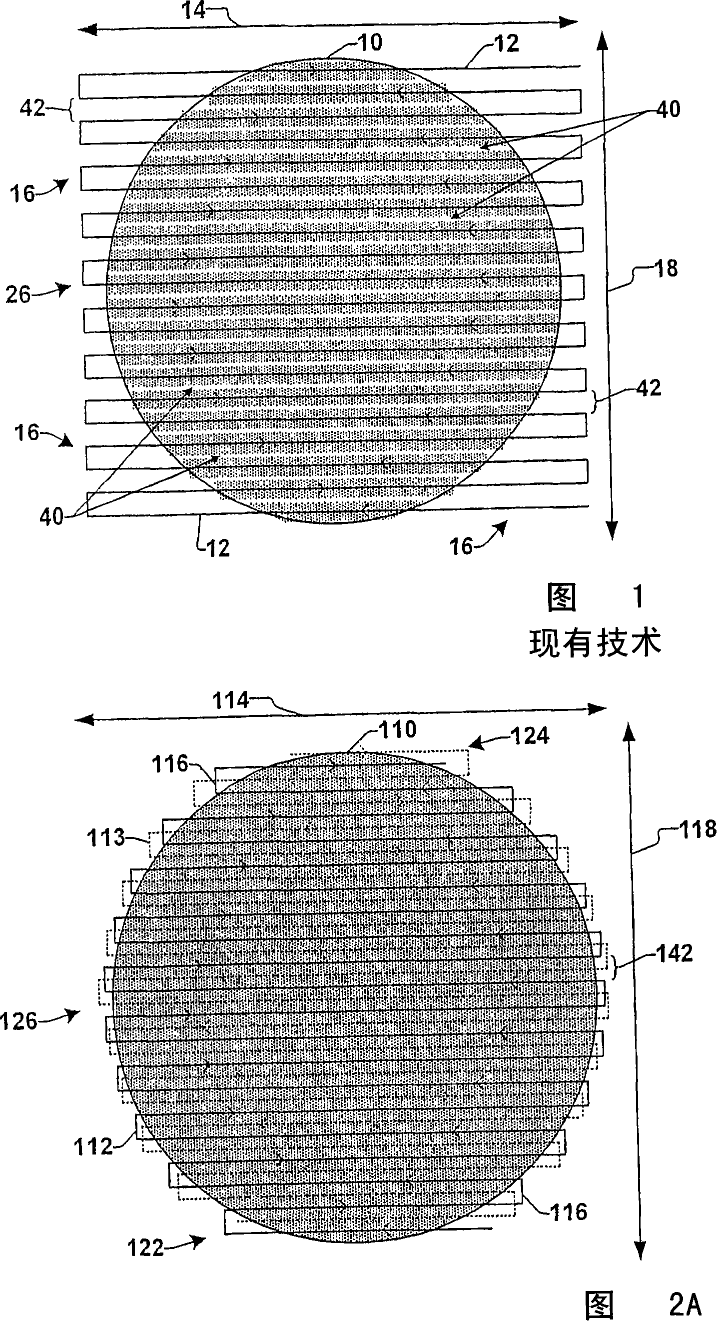
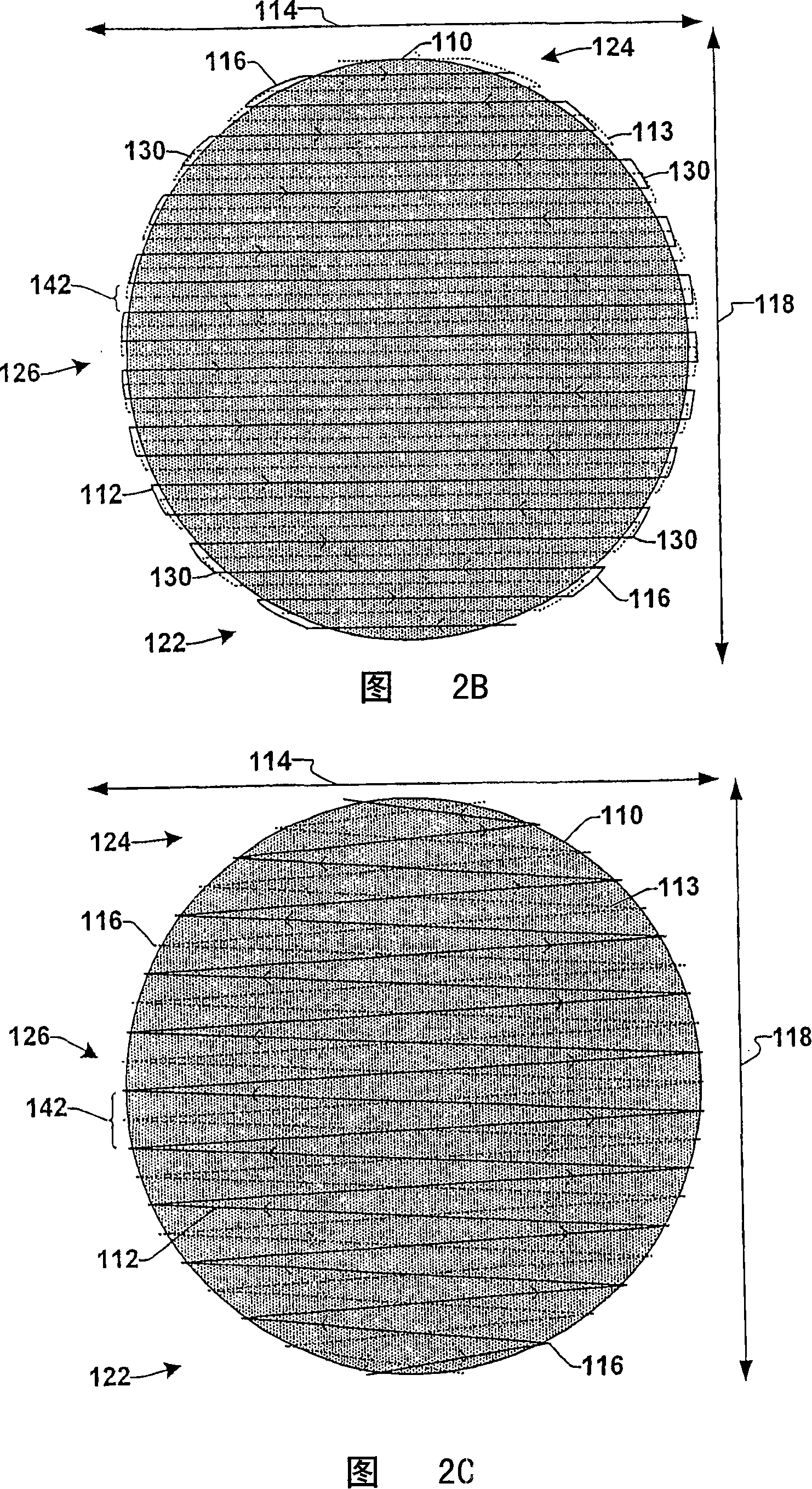
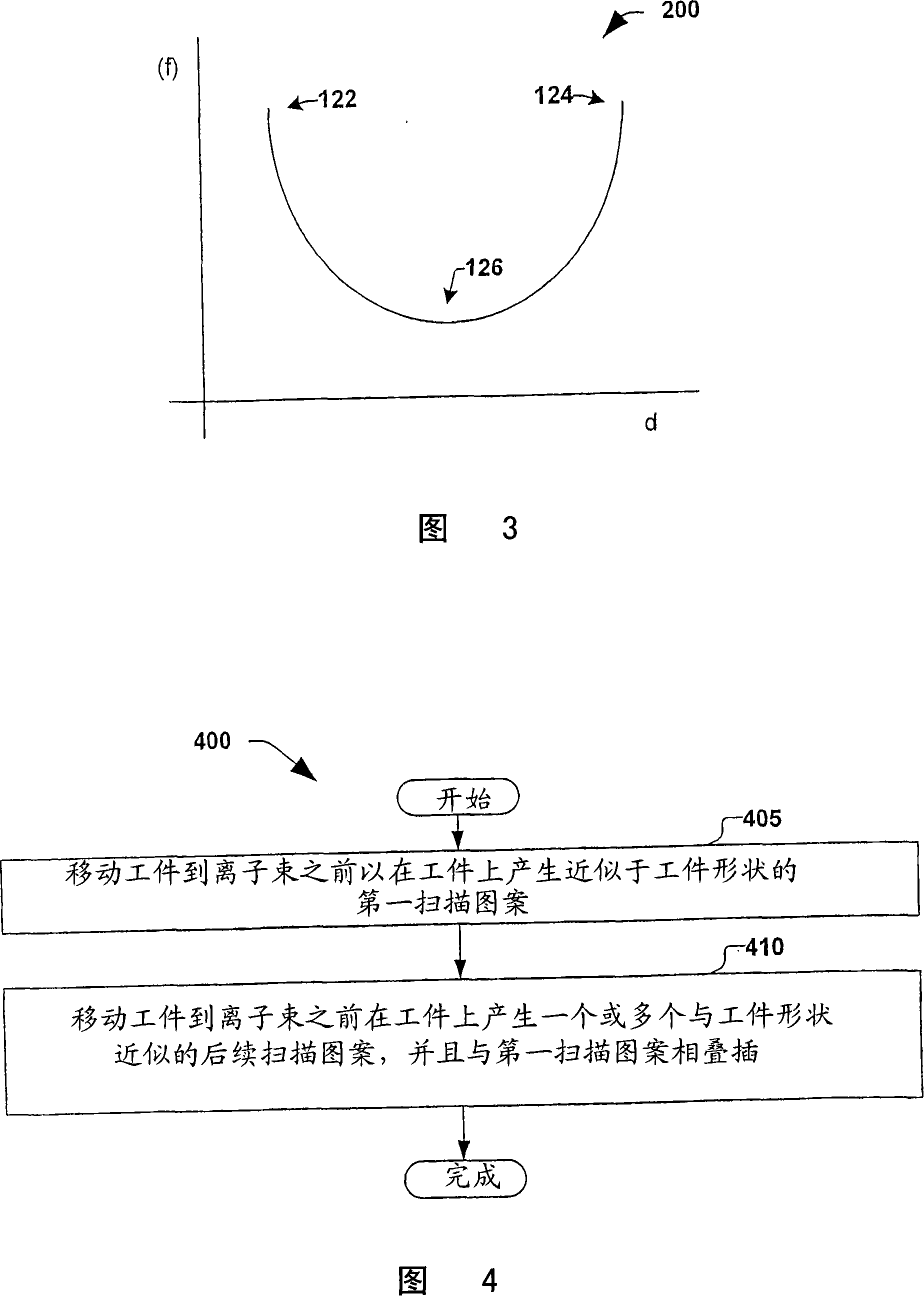
[0019] The present invention pertains to a workpiece or substrate that is moved relative to a substantially stationary ion beam to produce a scan pattern on the substrate that resembles the shape of the workpiece, and whereupon the scan patterns produced on the workpiece are interleaved so that uniform ion implantation becomes easy. One or more aspects of the present invention will now be described with reference to the drawings, wherein like numerals refer to like elements throughout. It should be understood that the drawings and the ensuing description are illustrative only and should not be viewed in a limiting manner. In the following description, for purposes of explanation, numerous specific details are set forth in order to provide a thorough understanding of the present invention. It will be apparent, however, to one of ordinary skill in the art that the present invention may be practiced without these specific details. It should therefore be understood that variatio...


PUM


Abstract

The present invention is directed to implanting ions in a workpiece in a serial implantation process in a manner that produces one or more scan patterns on the workpiece that resemble the size, shape and / or other dimensional aspects of the workpiece. Further, the scan patterns are interleaved with one another and can continue to be produced until the entirety of the workpiece is uniformly implanted with ions.

Description

technical field [0001] The present invention relates generally to semiconductor processing systems and, more particularly, to controlling movement of a substrate relative to an ion beam during ion implantation. Background technique [0002] In the semiconductor industry, various production processes are typically performed on a substrate (eg, a semiconductor workpiece) to achieve various results on the substrate. For example, ion implantation may be performed to achieve specific properties on or within the substrate, such as limiting the diffusivity of the substrate's dielectric layer by implanting specific types of ions. Traditionally, the ion implantation process is performed either as a batch process, where multiple substrates are processed simultaneously, or as a sequential process, where a single substrate is individually processed in the sequential process. For example, conventional high-energy or high-current batch ion implanters can be operated to obtain a short ion...

Claims


Application Information

Patent Timeline
Patent Type & Authority Applications(China)
IPC IPC(8): H01J37/317H01J37/20H01J37/302H01L21/687H01J37/304
CPCH01J37/3171H01J37/304H01L21/68764H01J37/20H01L21/265
Inventor M·葛瑞夫A·芮
Owner AXCELIS TECHNOLOGIES
Learn More