Method of determining dose uniformity of a scanning ion implanter

A technology of ion implantation and uniformity, which is applied in the direction of discharge tubes, semiconductor devices, electrical components, etc., and can solve rough and other problems

Inactive Publication Date: 2007-06-27
APPLIED MATERIALS INC
View PDF6 Cites 3 Cited by
  • Summary
  • Abstract
  • Description
  • Claims
  • Application Information

AI Technical Summary

Problems solved by technology

However, the method disclosed in this patent only provides an indication of the number of defective fast scans of the beam across each substrate, thus providing only a rough and rapid indication of the likelihood of a defective or incompletely implanted substrate

Method used


Image

  • Method of determining dose uniformity of a scanning ion implanter
  • Method of determining dose uniformity of a scanning ion implanter
  • Method of determining dose uniformity of a scanning ion implanter

Examples


Embodiment Construction

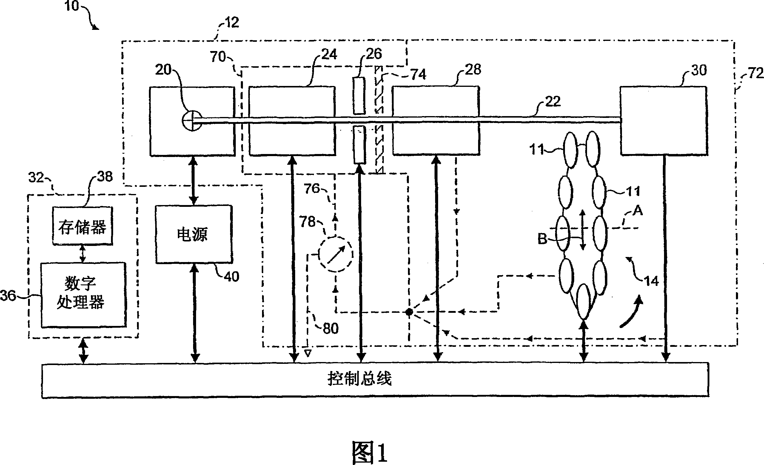
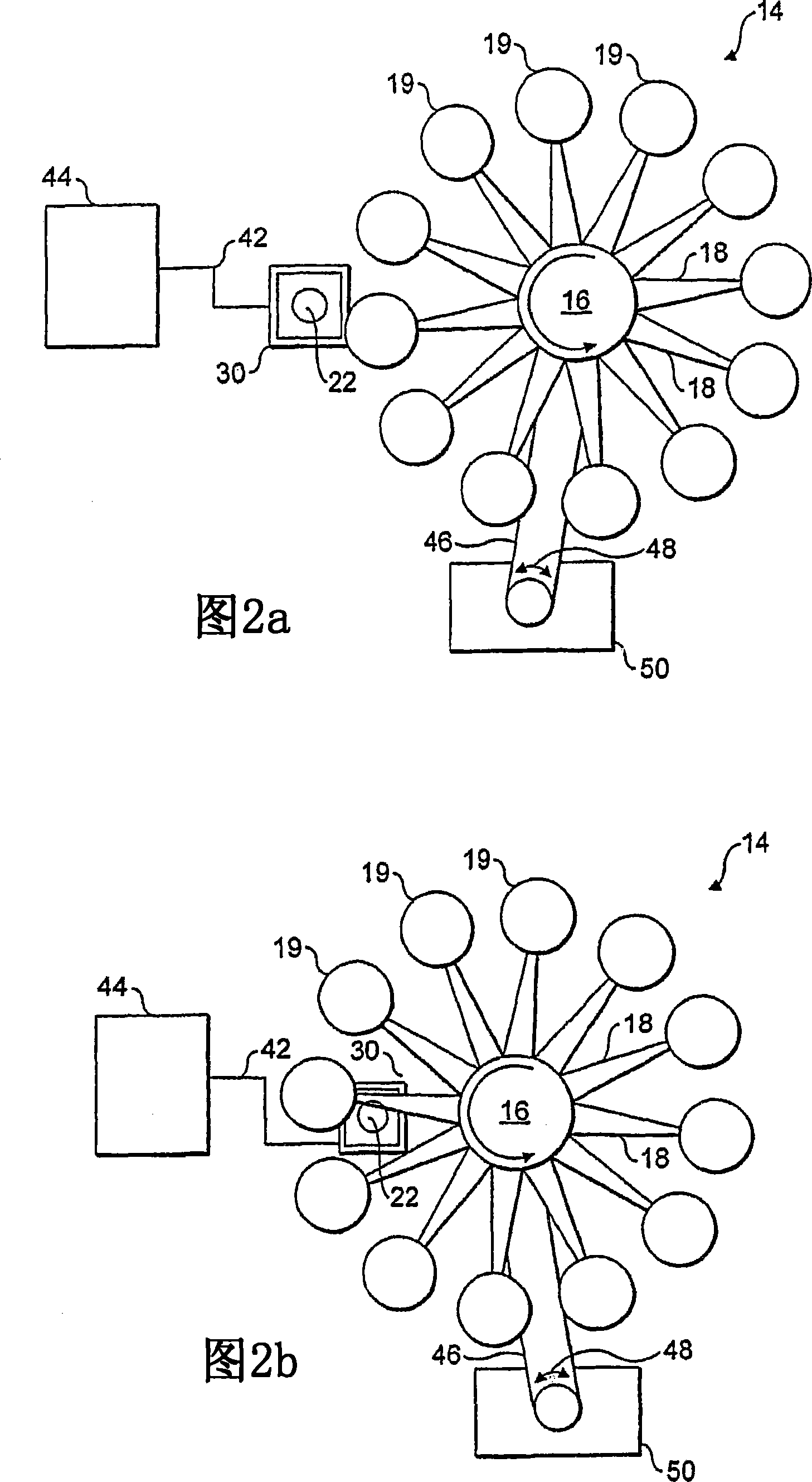
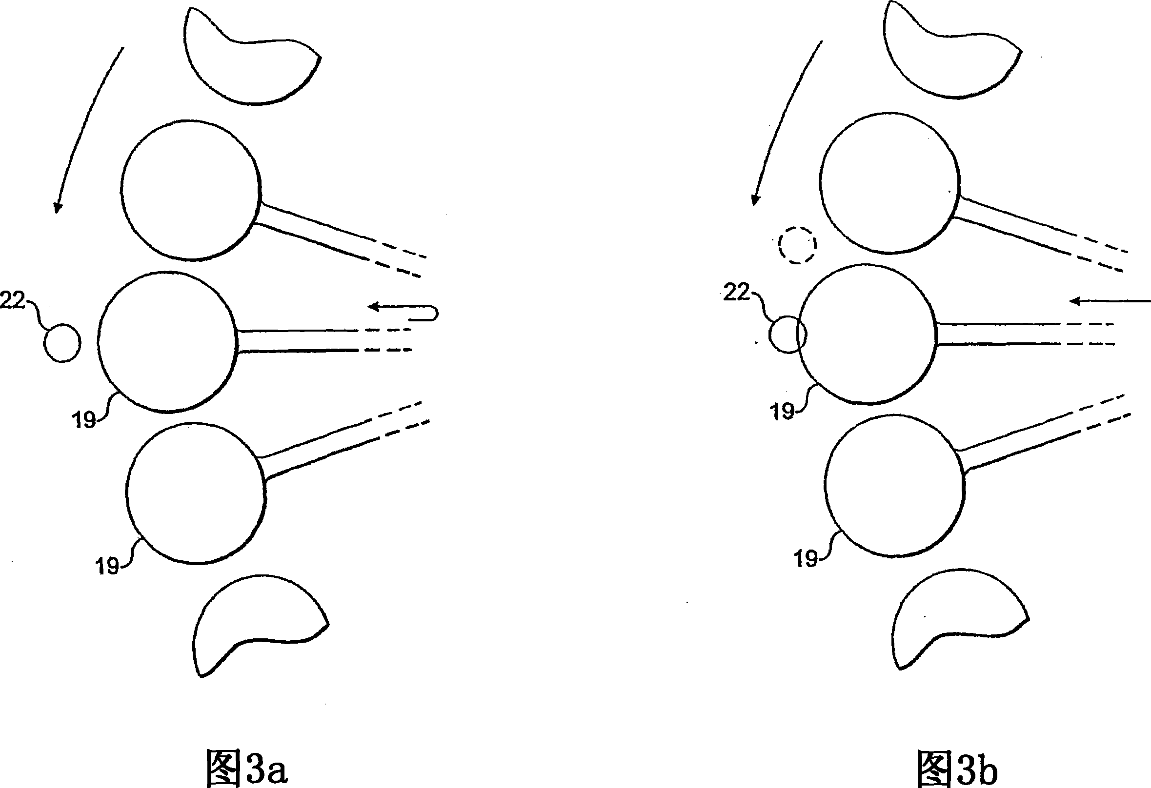
[0038] [0038] Referring to FIG. 1, the present invention can be embodied as a batch ion implanter 10 in which a plurality of substrate wafers 11 are placed in a vacuum chamber (which is collectively 12) is mounted around a spoked scan wheel 14 (shown only schematically in FIG. 1 and shown in more detail in FIG. 2). As shown in Figure 2, the scan wheel 14 comprises a hub 16 having radially extending spokes 18 supporting substrate holders 19, the substrate holders being equally spaced around the periphery of the wheel. In operation, wheel 14 rotates about axis A, while axis A reciprocates in the direction indicated by arrow B. As shown in FIG.

[0039] [0039] The ion implanter 10 further includes, within the vacuum chamber 12, an ion source 20 that produces a beam of ions directed toward a magnetic analyzer 24. Analyzer 24 typically includes a magnetic sector that causes ions to follow paths through a magnetic field that have a curvature that depends on the mass / charge ratio. ...


PUM


Abstract

Dose uniformity of a scanning ion implanter is determined. A base beam current is measured at the beginning and / or the end of a complete scan over the whole substrate area. This base beam current is measured at a time when the measurement should be unaffected by outgassing from a substrate being implanted and a base dose distribution map is then calculated for the scan in question. During the scan itself beam instability events are detected and the magnitude and position in the scan of the detected instability events is measured. Corresponding deviations in the calculated base dose map are determined and subtracted from the previously calculated base dose distribution map to provide a corrected distribution map. By determining overall dose uniformity substractively in this way, good overall accuracy can be obtained with lesser accuracy in the measurement of the beam instability events.

Description

technical field [0001] [0001] The present invention relates to ion implanters and, in particular, to methods of determining the uniformity of ion dose implanted onto a substrate by such implanters. Background technique [0002] [0002] Ion implanters can be used to alter semiconductor substrate materials by implanting ions of desired species into the substrate, thereby altering the properties of the substrate. [0003] [0003] Ion implantation occurs in a vacuum chamber in which a substrate or wafer to be ion-implanted is mounted on a holder. Ions are usually directed from an ion source in a beam to the substrate, and the beam cross-sectional area is usually smaller than the cross-sectional area of ​​the wafer to be implanted. For uniform implantation over the entire surface of the substrate wafer, a relative scan is provided between the substrate and the beam. [0004] [0004] Various scanning arrangements have been proposed and used in the prior art, including two-dimension...

Claims


Application Information

Patent Timeline
Patent Type & Authority Applications(China)
IPC IPC(8): H01J37/317H01J37/256
CPCH01J2237/31703Y10S438/961H01J37/3171H01J37/244H01J37/304H01J37/317H01J37/30H01J37/252
Inventor D·W·瓦格纳B·加洛P·T·金德斯利D·E·阿贝勒J·Y·西蒙斯
Owner APPLIED MATERIALS INC
Why Eureka
Try Eureka