Asymmetric Pulse Voltage Modulation Electron Beam Method Based on Suppression of Beam Instability

An unstable, pulsed voltage technology, applied in the direction of discharge tube electron guns, etc., can solve the problems of low efficiency and high cost, and achieve the effects of high precision, improved performance, and flexible combination

Active Publication Date: 2020-04-21
INST OF MODERN PHYSICS CHINESE ACADEMY OF SCI
View PDF2 Cites 0 Cited by
  • Summary
  • Abstract
  • Description
  • Claims
  • Application Information

AI Technical Summary

Problems solved by technology

At present, when using this modulation method, the velocity, distribution, and current intensity of the electron beam do not change. Although the DC electron beam signal is modulated into a sine wave electron beam signal, the electron beam is still continuous, and this feature cannot be used. Electron Beam Research Suppresses Instability of Heavy Ion Beams
Sine wave high-voltage modulation of the gate bias voltage can be used to suppress beam instabilities, but the cost of implementing such modulation is very high and the efficiency is very low

Method used


Image

  • Asymmetric Pulse Voltage Modulation Electron Beam Method Based on Suppression of Beam Instability
  • Asymmetric Pulse Voltage Modulation Electron Beam Method Based on Suppression of Beam Instability
  • Asymmetric Pulse Voltage Modulation Electron Beam Method Based on Suppression of Beam Instability

Examples


Embodiment 1

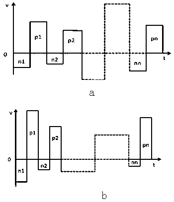
[0054] Embodiment 1: Narrow pulse modulation voltage waveform.

[0055] The trigger signal triggers the high-voltage switch, and the DC bias increases monotonously. An example of obtaining a set of asymmetric high-voltage pulse modulation waveforms is as follows Figure 8 , Figure 8 In -a, the positive amplitude of the DC bias is 600V, the absolute value ratio is 1.5:1 when the negative bias amplitude is -400, and the pulse width is 1us; Figure 8 In -b, the positive amplitude of the DC bias is 1200V, and the absolute value ratio is 3:1 when the negative bias amplitude is -400V, and the pulse width is 50us.

Embodiment 2

[0056] Embodiment 2: wide pulse modulation voltage waveform.

[0057] The trigger signal triggers the high-voltage switch, and the DC bias increases monotonously. An example of obtaining a set of asymmetric high-voltage pulse modulation waveforms is as follows Figure 9 , Figure 9 In -a, the positive amplitude of the DC bias is 600V, the absolute value ratio is 1.5:1 when the negative bias amplitude is -400, and the pulse width is 1ms; Figure 8 In -b, the positive amplitude of the DC bias is 1200V, and the absolute value ratio is 3:1 when the negative bias amplitude is -400V, and the pulse width is 200us.

[0058] The above-mentioned embodiments describe the characteristics of the asymmetrical high-voltage modulation pulse waveform, and the parameters of the enumerated examples are changed accordingly according to the experimental test requirements.


PUM


Abstract

The invention relates to a beam instability prevention-based asymmetric pulse voltage modulation electronic beam method. The method comprises the following steps of (1) modulating DC bias of a controlpole to a pulse voltage by a high-voltage pulse signal, wherein other basic parameters of the system are correspondingly changed according to modulation requirement; (2) triggering a logic driving circuit of a high-voltage switch by a trigger signal, and determining a frequency of a high-voltage pulse signal and pulse width of the high-voltage switch according to the frequency and the pulse widthof the trigger signal; (3) calculating the frequency of the high-voltage pulse signal according to a cyclotron frequency of an ion beam; (4) setting a modulation period T in an injection period; (5)setting the frequency fe and the pulse width Um of the trigger signal; (6) setting amplitude +U and -U of the DC bias; (7) setting an initial time Ts and an ending time Te of a synchronous time sequence control instruction of each modulation period; (8) setting a modulation mode; and (9) triggering a modulation system. The method has the advantage of flexible adjustment and combination and is easyto implement.

Description

technical field [0001] The invention relates to a method for modulating electron beams, in particular to an asymmetric pulse voltage modulating method for electron beams based on suppressing beam instability. Background technique [0002] Improving the beam quality has always been an important task of the heavy ion storage ring. When the DC electron beam and the heavy ion beam undergo Coulomb collisions, the quality of the heavy ion beam is effectively improved through multiple interactions between the two. Some heavy ion beam instabilities caused by this effect were observed, and it became necessary to suppress these instabilities. [0003] At present, a set of sine wave electron beam modulation system has been built, and the system composition is as follows: figure 1 As shown, the sine wave modulation signal is amplified, signal processed, and photoelectrically converted to the control electrode. When the gun area is in a proper DC electric field state, a DC electron beam...

Claims


Application Information

Patent Timeline
Patent Type & Authority Patents(China)
IPC IPC(8): H01J3/02
CPCH01J3/02
Inventor 马晓明杨晓东
Owner INST OF MODERN PHYSICS CHINESE ACADEMY OF SCI
Why Eureka
Try Eureka