Methods for rapidly switching off an ion beam

a technology of ion beam and ion beam, which is applied in the field of ion beam implantation system, can solve the problems of inability to detect instability and deviation in beam characteristics, and achieve the effects of reducing non-uniform implantation, rapid switching, and facilitating ion implantation

Active Publication Date: 2009-09-15
AXCELIS TECHNOLOGIES
View PDF21 Cites 12 Cited by
  • Summary
  • Abstract
  • Description
  • Claims
  • Application Information

AI Technical Summary

Benefits of technology

[0009]Aspects of the present invention facilitate ion implantation by detecting ion beam instabilities and mitigating non-uniform implantations. An ion beam generated by a non-arc discharge ion source can be rapidly switched off after detecting an instability and allow a controlled recovery and avoid a non-uniform dose for implantation.

Problems solved by technology

An instability is detected when one or more of the beam characteristics deviate from acceptable values or levels.

Method used


Image

  • Methods for rapidly switching off an ion beam
  • Methods for rapidly switching off an ion beam
  • Methods for rapidly switching off an ion beam

Examples


Embodiment Construction

[0026]The present invention will now be described with reference to the drawings wherein like reference numerals are used to refer to like elements throughout, and wherein the illustrated structures are not necessarily drawn to scale.

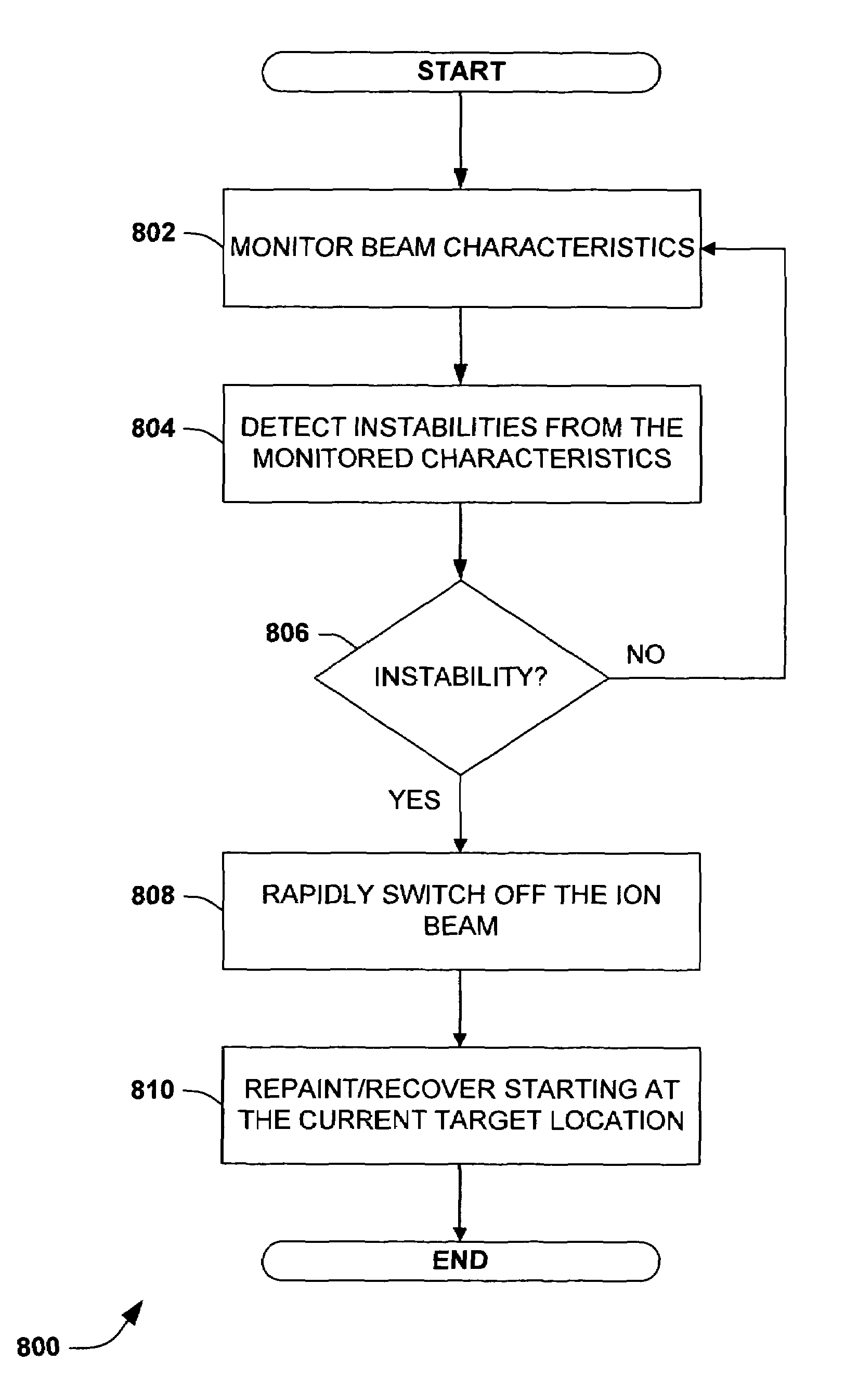
[0027]Aspects of the present invention facilitate ion implantation by detecting instabilities and performing repainting or recovery processes. As a result, non-uniform implantations, degradation of target workpieces and devices, and the like can be avoided and / or mitigated.

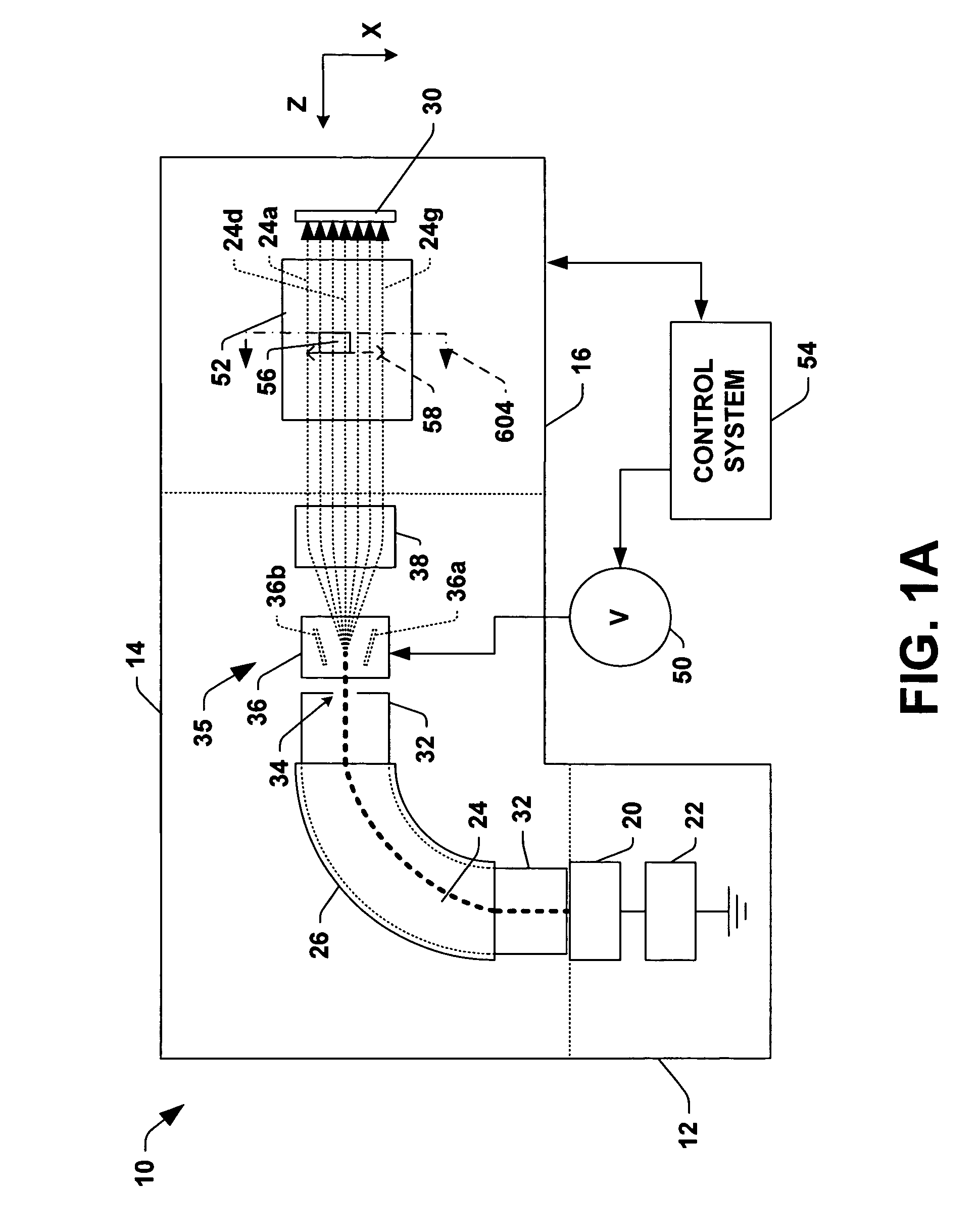
[0028]It is noted that the language “scanning an ion beam across a workpiece” merely implies relative motion of the ion beam with respect to the workpiece. Thus, it includes moving one or both of the ion beam and workpiece relative to each other. Example ion implantation systems are shown below that include several variations of scanning.

[0029]FIG. 1A is a diagram illustrating an exemplary ion implantation system 10 having a terminal 12, a beamline assembly 14, and an end station 16 w...


PUM


Abstract

An ion beam is rapidly switched off during ion implantation on detecting a beam instability. The ion beam is generated or provided by a non-arc discharge based ion source, such as an electron gun ion source or an RF ion source. The ion beam is scanned across a workpiece from a starting location toward an ending location. During the scanning, one or more beam characteristics are monitored, such as beam current, beam flux, shape, and the like. An instability is detected when one or more of the beam characteristics deviate from acceptable values or levels. The ion beam is rapidly turned off on the detected instability.

Description

FIELD OF THE INVENTION[0001]The present invention relates generally to ion implantation systems, and more specifically to improved systems and methods for uniformly scanning ion beams across a workpiece.BACKGROUND OF THE INVENTION[0002]In the manufacture of semiconductor devices and other products, ion implantation is used to dope semiconductor wafers, display panels, or other workpieces with impurities. Ion implanters or ion implantation systems treat a workpiece with an ion beam, to produce n or p-type doped regions or to form passivation layers in the workpiece. When used for doping semiconductors, the ion implantation system injects a selected ion species to produce the desired extrinsic material, wherein implanting ions generated from source materials such as antimony, arsenic or phosphorus results in n-type extrinsic material wafers, and implanting materials such as boron, gallium or indium creates p-type extrinsic material portions in a semiconductor wafer.[0003]Ion beams emp...

Claims


Application Information

Patent Timeline
Patent Type & Authority Patents(United States)
IPC IPC(8): H01J37/317H01J37/256
CPCH01J37/08H01J37/3045H01J37/3171H01J2237/043H01J2237/30472H01J2237/24535H01J2237/24564H01J2237/24578H01J2237/30455H01J2237/082
Inventor GRAF, MICHAEL A.EISNER, EDWARD C.DIVERGILIO, WILLIAM F.TIEGER, DANIEL R.
Owner AXCELIS TECHNOLOGIES
Why Eureka
Try Eureka