
System and method for reducing beam instability in laser annealing

A laser annealing, laser beam technology, applied in laser welding equipment, semiconductor/solid state device testing/measurement, manufacturing tools, etc., can solve problems such as reducing the uniformity of laser annealing process

Active Publication Date: 2019-12-13
VEECO INSTR
View PDF16 Cites 0 Cited by
  • Summary
  • Abstract
  • Description
  • Claims
  • Application Information

AI Technical Summary

Problems solved by technology

This phenomenon may reduce the uniformity of the laser annealing process

Method used


Image

  • System and method for reducing beam instability in laser annealing
  • System and method for reducing beam instability in laser annealing
  • System and method for reducing beam instability in laser annealing

Examples


Embodiment Construction

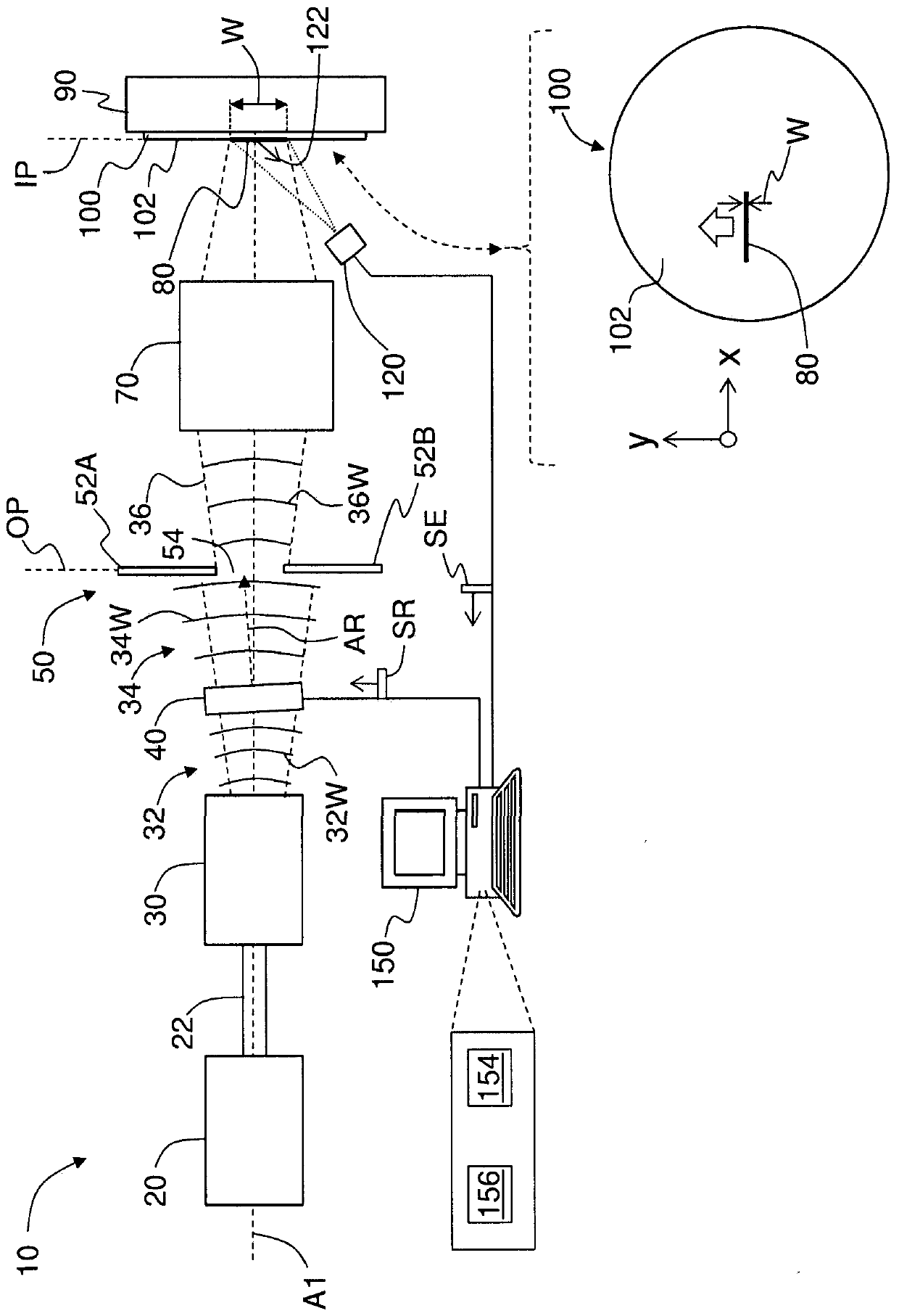
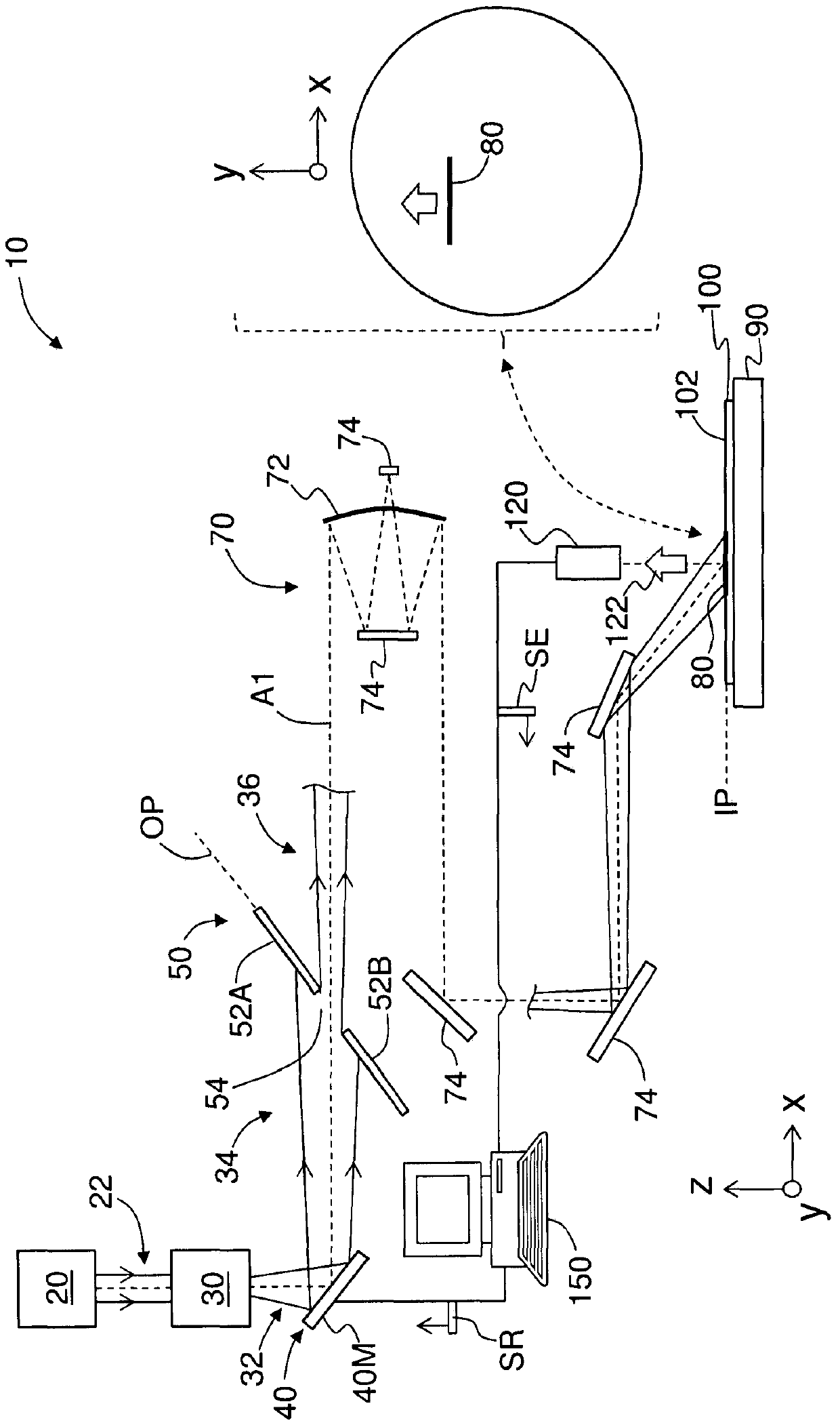
[0035] Reference will now be made in detail to the various embodiments of the present disclosure, examples of which are illustrated in the accompanying drawings. Wherever possible, the same or like reference numbers and symbols will be used throughout the drawings to refer to the same or like parts. The drawings are not necessarily to scale, and those skilled in the art will recognize where the drawings have been simplified to illustrate key aspects of the disclosure.

[0036] The claims set forth below are incorporated into and constitute a part of the Detailed Description.

[0037] Cartesian coordinates are shown in some figures for reference purposes and are not meant to limit direction or orientation.

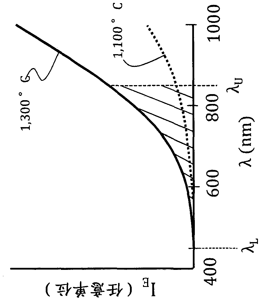
[0038] In the following discussion, certain functions such as line image intensity profile, annealing temperature profile, and thermal emission profile are time-varying and denoted as I L (x, t), T A (x, t) and E(x, t).

[0039] figure 1 is a schematic diagram of an ex...


PUM

PropertyMeasurementUnit
wavelengthaaaaaaaaaa

Abstract

The present invention relates to systems and methods for reducing beam instability in laser annealing. The method includes: directing a conditioning laser beam through an opening in an aperture with a beam redirecting element; forming a line image on the surface of the semiconductor wafer by imaging the aperture at the surface of the semiconductor wafer , thereby locally heating the surface of the semiconductor wafer to form an annealing temperature distribution; detecting thermal emission from the locally heated surface of the semiconductor wafer; determining the annealing temperature distribution based on the detected thermal emission; from the annealing a temperature profile to determine a line image intensity profile comprising a time variation of slope; and adjusting said beam redirecting element to redirect said adjusted laser beam to reduce or eliminate the slope in said line image intensity profile time variable.

Description

technical field [0001] The present disclosure relates to laser annealing, and more particularly to systems and methods for reducing beam instability in laser annealing. [0002] The complete disclosures of any publications or patent documents mentioned herein are incorporated by reference, including U.S. Patent Nos. .2013 / 0330844. Background technique [0003] In semiconductor manufacturing, laser annealing (also known as laser spike annealing, laser thermal annealing, laser thermal treatment, etc.) Dopants in selected regions of devices (structures) formed in a wafer. [0004] One type of laser annealing involves forming a line-shaped intensity profile that is scanned over the semiconductor wafer by moving a line image, moving the semiconductor wafer, or a combination of both. The line image is scanned along a "scanning direction" perpendicular to the long axis of the line image. Some spatial variation in the intensity of the line image along the scan direction (ie the ...

Claims


Application Information

Patent Timeline
Patent Type & Authority Patents(China)
IPC IPC(8): H01L21/268H01L21/67
CPCH01L21/268H01L21/67115H01L22/10H01L21/67248H01L22/26H01L21/324B23K26/034
Inventor J·T·麦克沃特A·哈夫雷鲁克S·阿尼基蒂切夫M·萨法
Owner VEECO INSTR
Learn More