Coupling structure for lock pin capable of idling

A technology of lock cylinder and front lock cylinder, which is applied in building locks, cylinder pin locks, building structures, etc., can solve problems such as inability to effectively prevent violent tools from prying and twisting lock cylinders, and achieve strong and destructive unlocking, The effect of improving the anti-theft performance

Inactive Publication Date: 2008-03-12
雷先鸣
View PDF2 Cites 2 Cited by
  • Summary
  • Abstract
  • Description
  • Claims
  • Application Information

AI Technical Summary

Problems solved by technology

A prominent problem in the lock cylinder of this structure is that it cannot effectively prevent violent tools from prying and twisting the lock cylinder.

Method used


Image

  • Coupling structure for lock pin capable of idling
  • Coupling structure for lock pin capable of idling
  • Coupling structure for lock pin capable of idling

Examples


Embodiment Construction

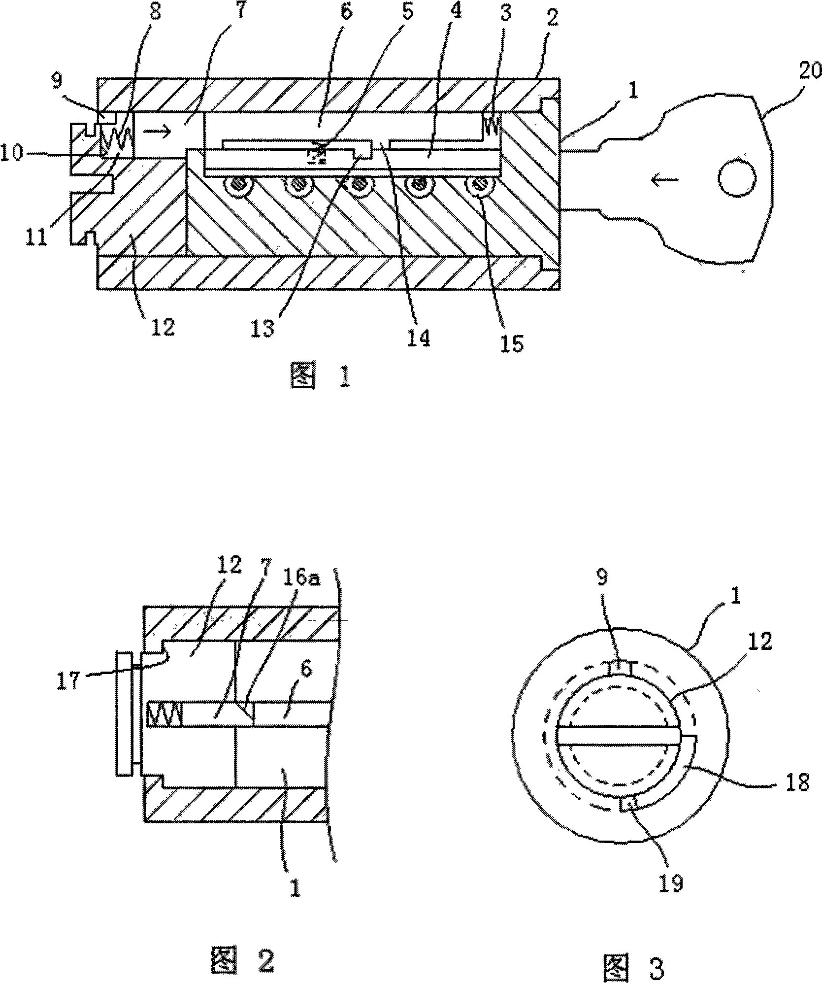
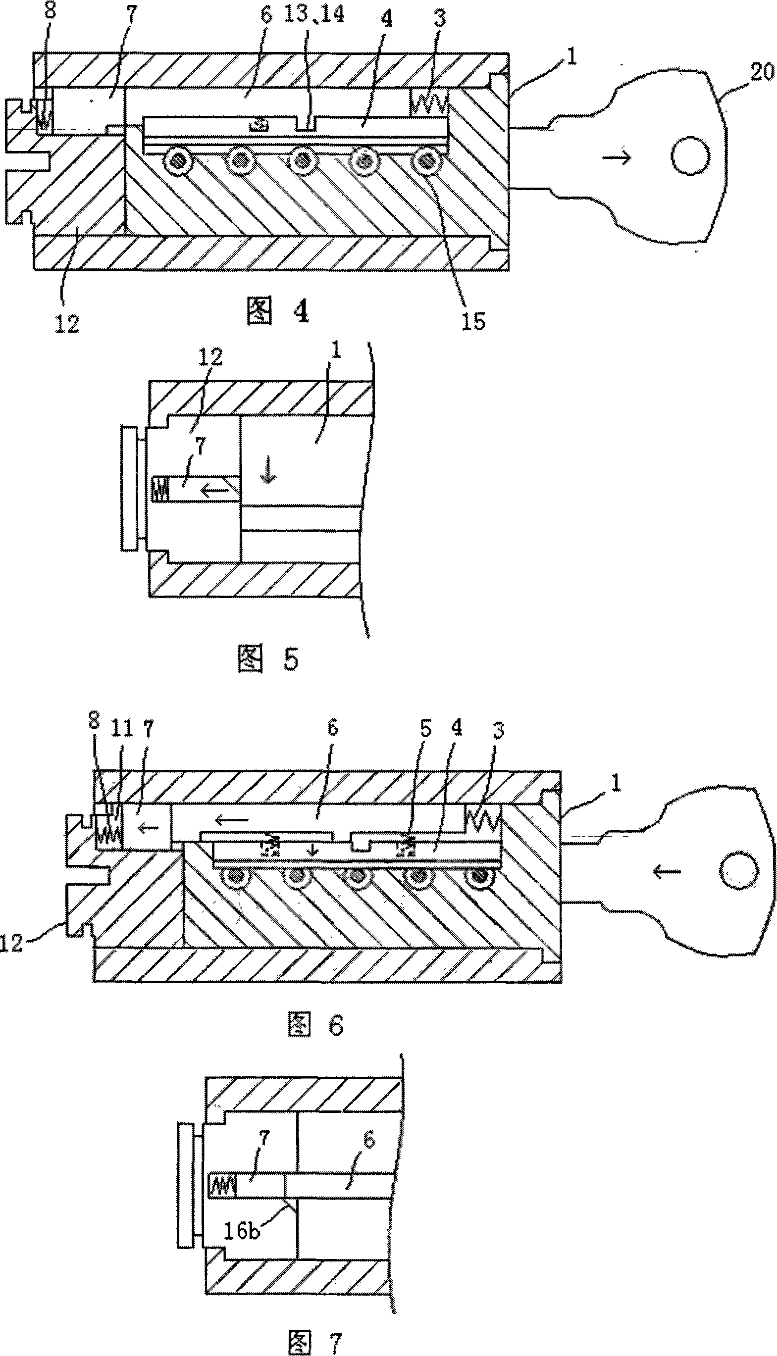
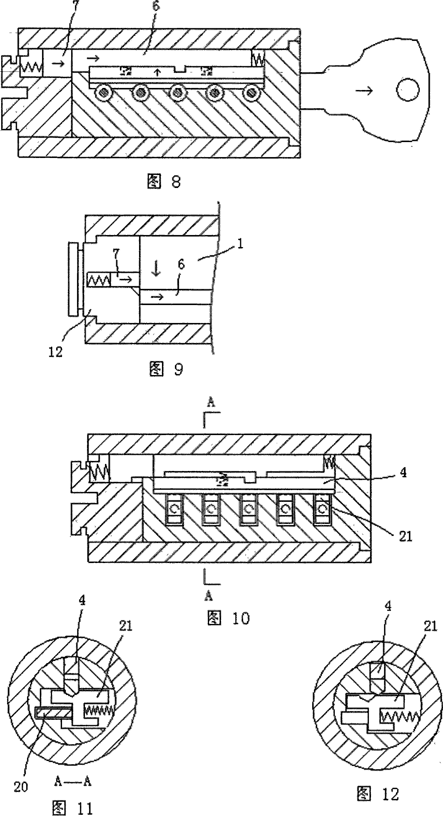
[0020] An embodiment of the clutch structure that the lock core of the present invention can idle is shown in Fig. 1, including a front lock core 1 and a rear lock core 12. The matching locking side column 4 and sliding block 6, the sliding block 6 and the locking side column 4 are respectively provided with a protrusion 14 (groove) and a groove 13 (protrusion) that can be matched, and the locking side column 4 and sliding block 6 A locking side post return spring 5 is provided between them, and a sliding block return spring 3 is provided between the sliding block 6 and the end wall of the locking side post slot; on the rear lock core 12, it corresponds to the locking side post slot in the front lock core 1 Lock pin chute 11 is set, and lock pin chute 11 has end wall 10 at the afterbody of rear lock core, and lock pin 7 is placed in lock pin chute 11, between end wall 10 in lock pin chute 11 and lock pin 7 Lock pin return spring 8 is arranged between; The elasticity of lock pi...


PUM


Abstract

The invention discloses a clutch structure with an idling lock core, and comprises a lock core inside a lock body. The lock core is composed of a front lock core and a rear lock core; a side lock bar slot on the front lock core comprises a side lock bar and a slider; the slider and the side lock bar are respectively arranged with a boss (matching with a groove) and a groove (matching with a boss); a slider resetting spring is positioned between the slider and the end wall of the side lock bar slot; a latch pin runner is arranged on the side lock bar slot on the rear lock core and corresponds with the front lock core; the latch pin runner inside is positioned with a latch pin; a latch pin resetting spring is arranged between the end wall, inside the latch pin runner and the latch pin; elasticity of the latch pin resetting spring is higher (smaller) than that of the slider resetting spring; at least one of the latch pin (slider) and the side lock bar slot wall (latch pin runner wall) adopts a slope to contact with the other one. The lock with the invented lock core clutch structure can effectively prevent damaging and unlocking the lock core with violent tools.

Description

technical field [0001] The invention belongs to mechanical locks, and relates to a clutch structure in which a pin lock core and a blade lock core can rotate idly. Background technique [0002] The pin lock and leaf lock locked by the existing side column structure, in the locked state, the lock cylinder can not rotate relative to the lock body. A prominent problem that the lock cylinder of this structure exists is: can not effectively prevent violent tool from prying and twisting the lock cylinder. If you use a strong enough lockpicking tool to forcibly twist the lock cylinder, the bolt fixing the lock head can be twisted off. Contents of the invention [0003] The object of the present invention is to provide a clutch structure in which the lock cylinder can rotate idly in view of the above situation. The lock cylinder adopting the clutch structure can realize idle rotation, and effectively prevent violent tools from prying and twisting the lock cylinder to unlock. [...

Claims


Application Information

Patent Timeline
Patent Type & Authority Applications(China)
IPC IPC(8): E05B15/00E05B27/00E05B29/00
Inventor 雷先鸣
Owner 雷先鸣
Why Eureka
Try Eureka