
Arc helix cylindrical gear and arc rack

A technology of cylindrical gears and helical teeth, which is applied in belts/chains/gears, components with teeth, portable lifting devices, etc., can solve the problems that cannot be popularized and applied, and achieve the effect of stable transmission

Inactive Publication Date: 2008-03-26
完颜学明 +2
View PDF0 Cites 10 Cited by
  • Summary
  • Abstract
  • Description
  • Claims
  • Application Information

AI Technical Summary

Problems solved by technology

So far, it has not been well promoted and applied.

Method used


Image

  • Arc helix cylindrical gear and arc rack
  • Arc helix cylindrical gear and arc rack

Examples


Embodiment Construction

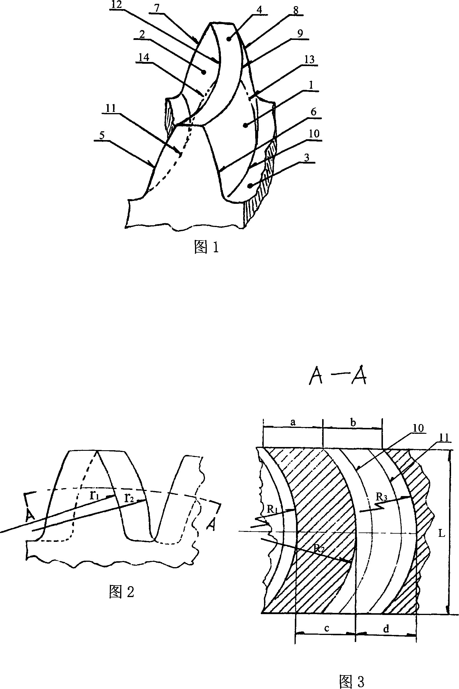
[0026] The main structure of the gear teeth of the present invention is as shown in Figure 1: it consists of a convex tooth surface 1, a concave tooth surface 2, a dedendum 3, and an addendum 4. The midpoint cross-sectional contour lines 13 and 14 of the tooth length L are the involute tooth profile of the spur gear, which respectively follow the convex arcs 9 and 10 on the convex tooth surface 1 and the concave surfaces 11 and 12 on the concave tooth surface 2 to both ends. Helical to positions 5, 6, 7, and 8 of the contour involutes on both ends of the gear tooth, forming a bidirectional helical tooth formed by a bidirectional helical tooth line with a right-handed arc-shaped helical tooth at one end and a left-handed arc-shaped helical tooth at the other end. The radius of curvature of the involutes of arc-shaped helical teeth 5, 6, 7, and 8 at both ends is greater than the radius of curvature of the involutes at the midpoints 13 and 14 of the tooth length, (as shown in Figu...


PUM


Abstract

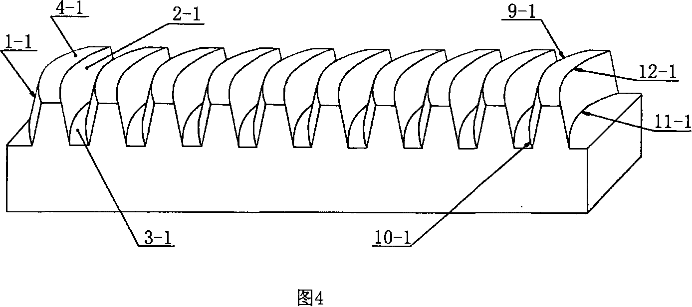
The present invention discloses one kind of curved teeth helical cylindrical gear and curved teeth helical rack. The curved teeth helical cylindrical gear has teeth comprising convex tooth face, concave tooth face, tooth root and tooth crest, and gear teeth cross section contour line comprises involutes, convex arc lines and concave arc lines to constitute bidirectional arc spiral line. The curved teeth helical rack has teeth comprising convex tooth face, concave tooth face, tooth root and tooth crest. The curved teeth helical cylindrical gear and the curved teeth helical rack have precise mesh path, 100 % contact surface, great bearing capacity and long service life.

Description

technical field [0001] The invention relates to a transmission gear, in particular to an arc helical cylindrical gear and an arc helical rack. Background technique [0002] Gear transmission is the most widely used form of transmission. At present, there are three forms of cylindrical gear "tooth line": spur gear (spur gear), helical gear (helical gear), herringbone gear (double helical gear) and the fourth form " "Circular tooth line cylindrical gear" is the research subject of "curved tooth line meshing form" published by the United States in 1975. The samples exhibited at the International New Technology Exhibition in 1986 had an involute tooth shape in the central section of the tooth width, and the shape and position were approximate values ​​away from the center. The contact surface of the "tooth line" did not generate local loads, and the three precisions did not match the ideal shape. Therefore, there have been many patent application titles on this subject since 19...

Claims


Application Information

Patent Timeline
Patent Type & Authority Applications(China)
IPC IPC(8): F16H55/17F16H55/26F16H55/08
Inventor 完颜学明完颜志翰完颜严
Owner 完颜学明
Learn More