Lifting gear of cap whirling machine

A lifting device and capping machine technology, which is applied in the direction of capping containers tightly with caps, packaging, threaded bottle caps, etc., can solve the problems of not ideally meeting the packaging requirements of screw caps, errors, and low production efficiency.

Inactive Publication Date: 2012-01-25
常州市金坛中正包装机械科技有限公司
View PDF2 Cites 2 Cited by
  • Summary
  • Abstract
  • Description
  • Claims
  • Application Information

AI Technical Summary

Problems solved by technology

[0003] ①The production efficiency is low, only one bottle cap can be tightened at a time
[0004] ②During the capping process, since the bottle body is pushed up by the end face cam and the tappet, the distance between the bottle mouth and the screw cap joint is a fixed value, and there are errors in both the bottle body and the bottle cap, and they are different from the bottle body. The contact and compression method of the cap is a rigid compression method, and the probability of crushing the bottle cap or not being able to press the bottle cap is high, which cannot ideally meet the packaging requirements of screw caps

Method used


Image

  • Lifting gear of cap whirling machine
  • Lifting gear of cap whirling machine
  • Lifting gear of cap whirling machine

Examples


specific Embodiment approach

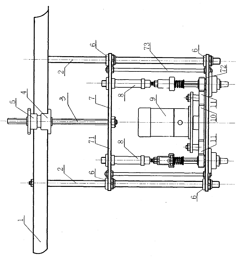
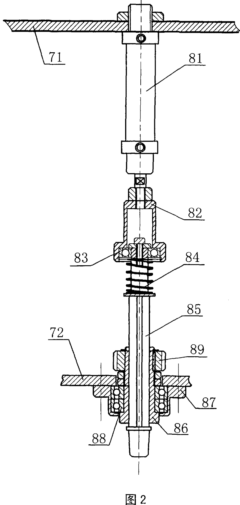
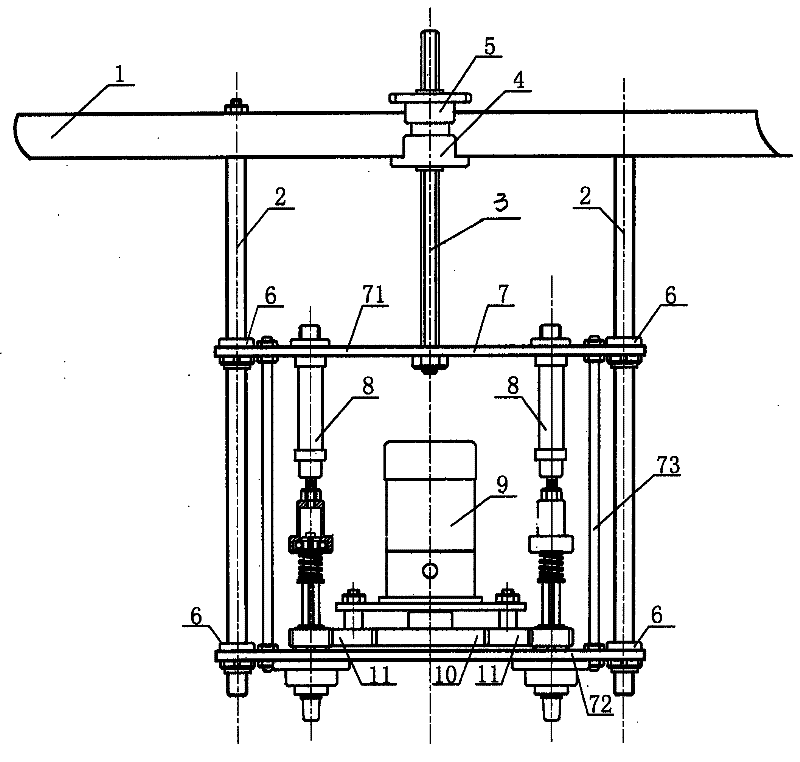
[0015] The cylinder telescopic capping device of the capping machine of the present invention includes a beam 1, a guide column 2, a lifting screw 3, a nut seat 4, an adjusting hand wheel 5, a sliding sleeve 6, a support frame 7, and two rotating telescopic parts 8 , motor 9, motor gear 10 and bridge gear 11, beam 1 is fixed on the frame by two guide columns 2; support frame 7 is made up of upper slide plate 71, lower slide plate 72, fixed rod 73, upper slide plate 71 and lower slide plate 72 is connected into a frame structure by two fixed rods 73, and the support frame 7 is set on the two guide posts 2 through four sliding sleeves 6 installed on the upper slide plate 71 and the lower slide plate 72, and the lifting screw rod 3 passes through and is fixed on the The nut seat 4 on the crossbeam 1, the lower end of the lifting screw 3 is fixed on the support frame 7, and the rotation adjustment handwheel 5 can make the support frame lift; The spring 84, the lifting rotating rod...


PUM


Abstract

A screw cover retractor device of a screw cover machine comprises a supporting frame, two screw retractor components, a motor, a motor gear and a gear idle. The screw retractor components are arranged at the supporting frame. The motor drives the screw retractor components turning by the gear idle. The flexing of screw cover tie-ins is drove by a cylinder. The cylinder is communicated with pressure air source and controlled by a control circuit. Adopting the device, a motor can synchronously drive two screw retractor components and can synchronously and tightly screw two covers once, screwingcover efficiency can be increased by one time by comparing with the prior technology. By adopting quick disappearing end bumper of the cylinder driving disappearing end bumper axis of rotation, the rapid flexible prepressing approach of the screw cover tie-ins and the covers is implemented. A reset spring can ensure the bottle covers and the bottle mouths are in a compressing condition all the time and can also automatically adjust bottle cover winding moment to ensure the screw cover tie-ins wind up the moments of the bottle covers, etc, automatically avoid screwing loosely or in a fracturedstate due to dimension errors of the bottle covers and the bottle height.

Description

Technical field: [0001] The invention relates to a bottle filling machine or capping machine, in particular to a capping lifting device. Background technique: [0002] The bottle capping machines commonly used now are disc-type capping machines, which consist of a continuously rotating circular worktable and several capping joints distributed in the same circle. The capping joints are located above the circular workbench. The height does not change when working, and there are bottle placement stations corresponding to the screw cap joints on the disc, and bottle body lifting devices corresponding to each bottle body station on the circular workbench, all lifting devices are controlled by It consists of a tappet and an end cam. When the tappet on the turntable turns to the highest point of the end cam, the bottle cap is in the tightening position. There is only one tightening station among all the stations on the turntable. The disc rotates continuously, and the bottle caps a...

Claims


Application Information

Patent Timeline
Patent Type & Authority Patents(China)
IPC IPC(8): B67B3/20B67B3/28
Inventor 李卫庆汤正平
Owner 常州市金坛中正包装机械科技有限公司
Why Eureka
Try Eureka