
Lighting fixture for vehicle

A technology for vehicles and lamps, which is applied to vehicle parts, lighting and heating equipment, optical observation devices, etc., can solve the problems of reducing the decorative quality of vehicle lamps and lanterns, and achieve the effects of improving decoration, suppressing brightness deviation, and suppressing visual recognition.

Inactive Publication Date: 2008-04-23
ICHIKOH IND LTD
View PDF1 Cites 3 Cited by
  • Summary
  • Abstract
  • Description
  • Claims
  • Application Information

AI Technical Summary

Problems solved by technology

In this way, the state of each LED can be visually observed when the lights are not turned on, which leads to a reduction in the decorativeness of the vehicle lamps when the lights are not turned on.

Method used


Image

  • Lighting fixture for vehicle
  • Lighting fixture for vehicle
  • Lighting fixture for vehicle

Examples


Embodiment 1

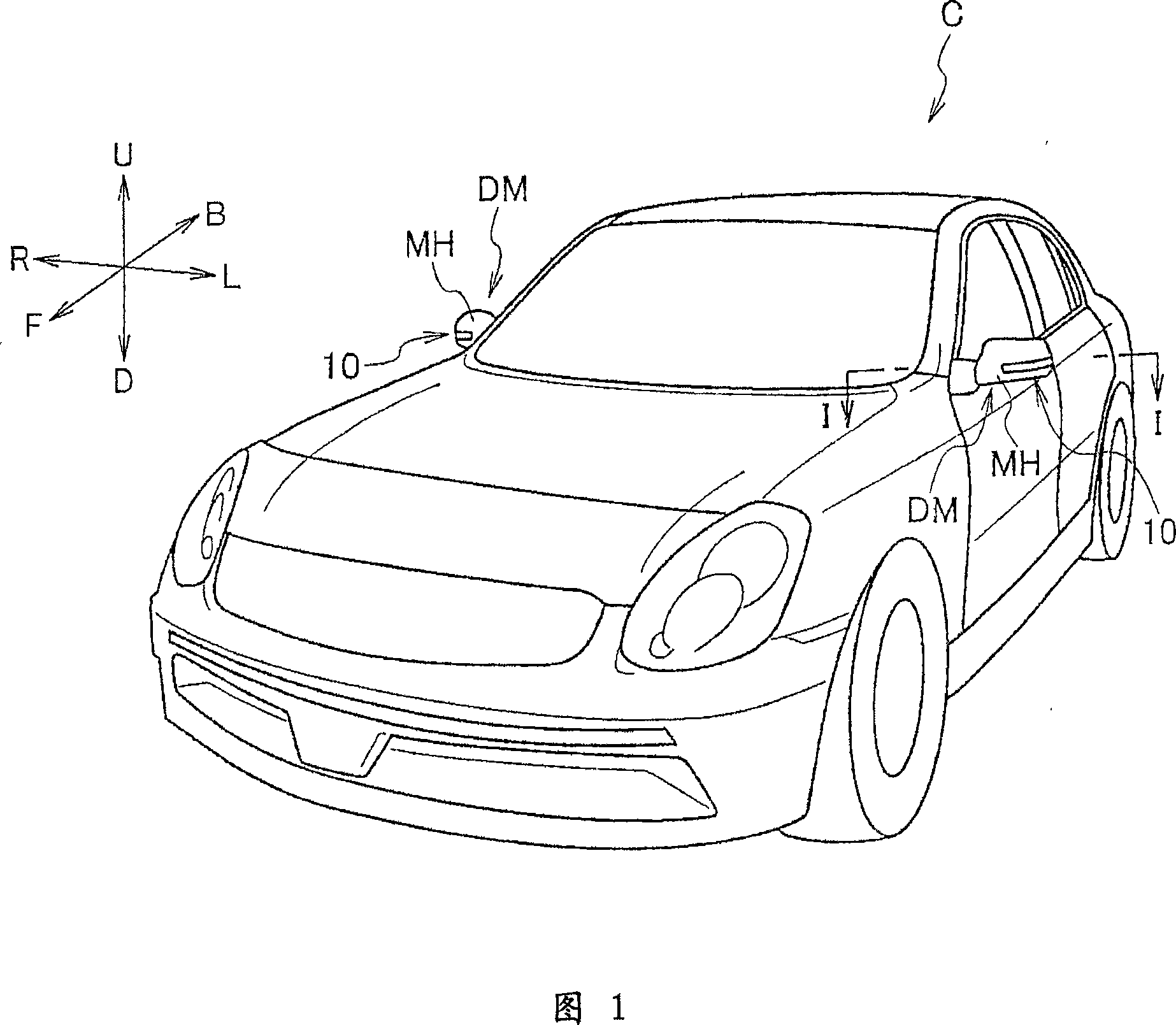
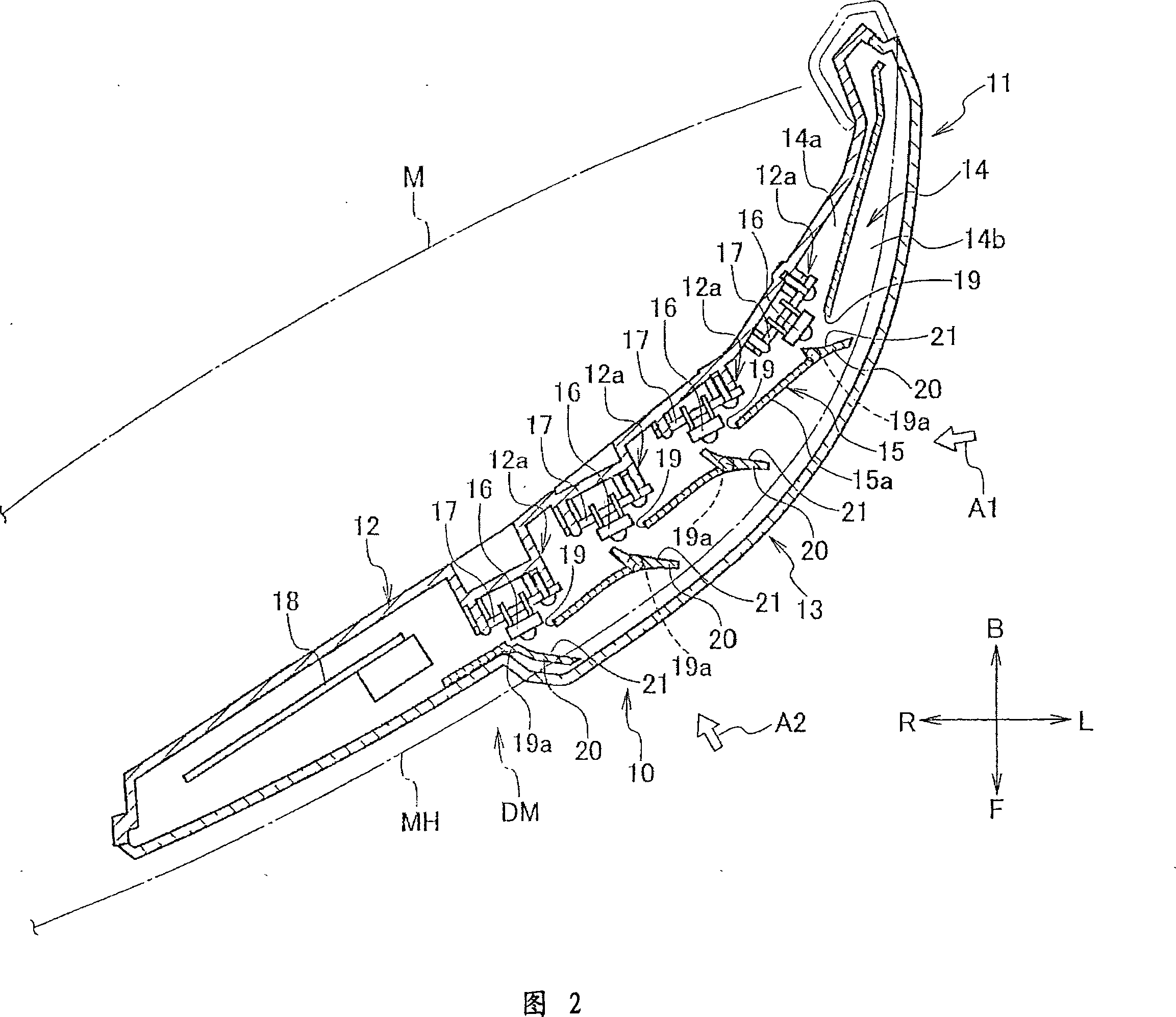
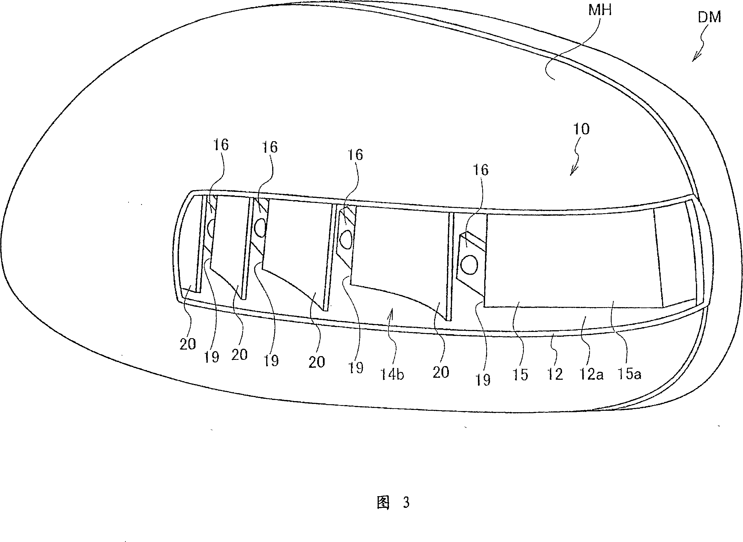
[0031] FIG. 1 is a schematic perspective view showing a vehicle C to which a vehicle lamp 10 of the present invention is applied. FIG. 2 is a schematic cross-sectional view showing the vehicle lamp 10 along line I-I shown in FIG. 1 . 3 is a schematic explanatory view showing the vehicle lamp 10 and its surroundings seen from the arrow A1 shown in FIG. Schematic illustration. In FIGS. 3 and 4 , the outer lens 13 described later is omitted for easy understanding. Hereinafter, as shown by the arrows in FIG. 1, U and D are used to indicate the up-down direction, L and R are used to indicate the left-right direction (also referred to as the width direction), and F and B are used to indicate the front-rear direction, as viewed from the interior occupant of the vehicle C, Each direction according to these will be explained.

[0032] As shown in FIG. 1 , a vehicle lamp 10 is provided in a mirror housing MH of a door mirror DM of a vehicle C. As shown in FIG. The door mirror DM is ...

Embodiment 2

[0056] Embodiment 2 of the vehicle lamp 210 according to the present invention will be described with reference to FIGS. 6 to 9 . Example 2 is an example in which the structure of the partition wall 215 and the mounting structure of each LED 16 are different from the vehicle lamp 10 of the example 1. Therefore, the vehicular lamp 210 of the second embodiment basically has the same structure and function as the vehicular lamp 10 of the first embodiment, and a detailed description of the same structure is omitted, and a detailed description of the same function is also omitted.

[0057] As shown in FIG. 6, in the vehicle lamp 210, the partition wall 215 is the same as the partition wall 15 of the first embodiment. In the space 14, the casing main body 212 is straddled in the vertical direction, but the structure of the opening 219 is different from that of the partition wall 15 of the first embodiment.

[0058] As shown in FIG. 7 , the opening 219 is partially opened in a subst...


PUM


Abstract

The present invention provides a vehicular lamp capable of suppressing visible luminance variation of a light source in a lit state and suppressing visual inspection of a light source in a non-lit state for irradiating light visible through an outer lens. A lamp (10) for a vehicle, by accommodating a light source (16) in a storage space (14) of a housing (11) having an outer lens (13) disposed on the side of the vehicle, a housing main body (12) and a partition wall (15) , using the emitted light from the light source and passing through the outer lens to form the irradiating light irradiating the side of the vehicle. An opening (19) is provided on the partition wall (15) and a light source is shielded to prevent the light source (16) from being viewed from the front in the front-rear direction of the vehicle, and the emitted light from the light source is reflected to the side of the vehicle in order to expand the irradiation area. The reflective surface (21) and the reflective wall part (20) extending to the exposed part (14b) of the storage space; the irradiation light is formed by the reflected light emitted from the reflective surface through the above-mentioned outer lens.

Description

technical field [0001] The present invention relates to a lamp for a vehicle, in particular to a lamp for a vehicle which is suitable for being arranged on a door reflector. Background technique [0002] It has been known in the past that the reflector housing of the door reflector of a vehicle is provided with a lamp housing for accommodating a plurality of LEDs arranged in a row as a light source and having an outer lens and a housing main body (for example, refer to Patent Document 1-Japan Japanese Patent Laid-Open No. 2002-79885). [0003] In the conventional lamps for vehicles, in order to meet the standards (statutory standards) to be used as a single lamp, there are lamps in which each LED is arranged so that the outgoing light from each LED is directed toward the outer lens, Accordingly, the irradiated areas formed on the outer lens are adjacent to each other at a smaller than predetermined interval, and all the LEDs are set to be turned on at the same time. Such a...

Claims


Application Information

Patent Timeline
Patent Type & Authority Applications(China)
IPC IPC(8): F21V13/00F21S8/10
CPCB60Q1/2665F21Y2101/02B60R1/1207F21Y2115/10B60Q1/32B60R1/06
Inventor 矢岛康雄冈田悟
Owner ICHIKOH IND LTD
Learn More