
Image distortion correction circuit and display device

A technology for distortion correction and circuit correction. It is used in image enhancement, transportation and packaging, and image data processing. It can solve problems such as circuit malfunction and damage to the mapping data itself.

Pending Publication Date: 2021-10-01
LAPIS SEMICON CO LTD
View PDF1 Cites 0 Cited by
  • Summary
  • Abstract
  • Description
  • Claims
  • Application Information

AI Technical Summary

Problems solved by technology

[0006] In addition, in such a circuit device, due to deterioration over time, etc., the circuits performing the mapping processing may become vulnerable to noise and malfunction, or the mapping data itself stored in the nonvolatile memory may be damaged.

Method used


Image

  • Image distortion correction circuit and display device
  • Image distortion correction circuit and display device
  • Image distortion correction circuit and display device

Examples


Embodiment Construction

[0027] figure 1 It is a block diagram showing the configuration of a head-up display device 100 (hereinafter referred to as HUD device 100 ) as a display device including the image distortion correction circuit of the present invention. The HUD device 100 projects a display image based on an input image signal onto a projection surface to generate a projection image, such as figure 1 As shown, it includes a distortion correction data memory 10 , a controller 11 , a distortion correction circuit 12 , a table memory 13 , an abnormality processing part 14 and an image irradiation part 15 .

[0028] The controller 11 generates an image signal representing driving support information such as behavior of the vehicle, instantaneous fuel consumption, state of the battery, traveling speed, etc. in characters or graphics. Furthermore, when the controller 11 receives the abnormality sensing signal ER indicating that an abnormality has occurred, it generates an image signal indicating th...


PUM


Abstract

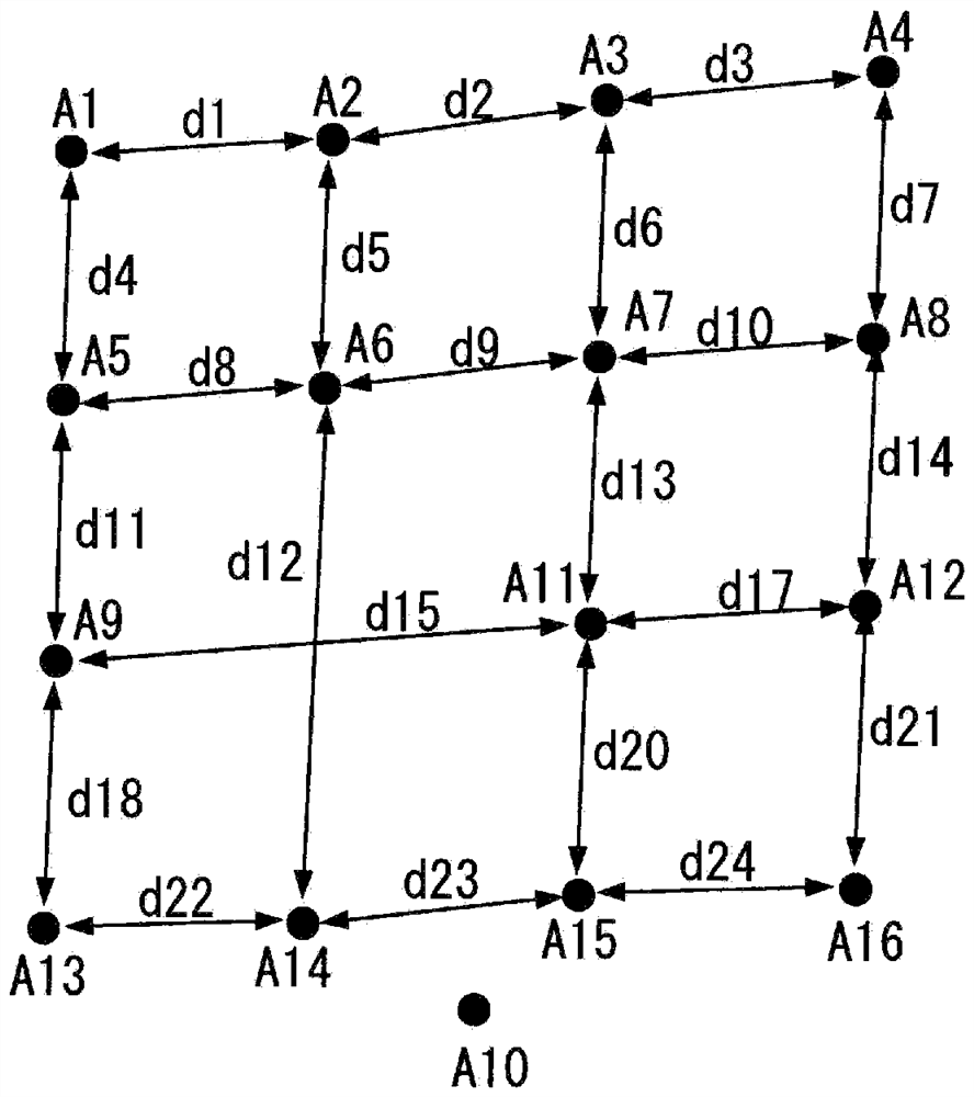
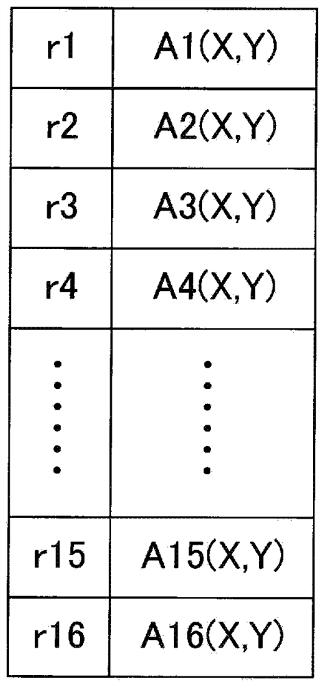
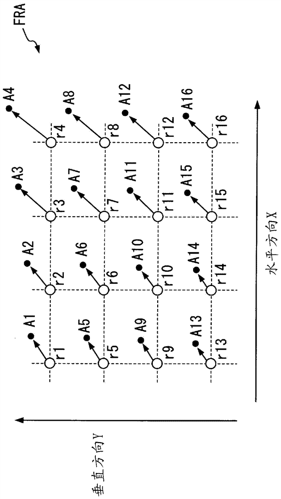
The purpose of present invention is to provide an image distortion correction circuit and a display device capable of displaying visually recognizable information even if abnormality occurs in distortion correction data for distortion correction. The image distortion correction circuit performs a distortion correction process on an image signal on the basis of distortion correction data to generate a distortion-corrected image signal. The distortion correction data is for correcting coordinate positions of display data fragments corresponding to respective N coordinate positions in the display image to first to N-th distortion correction coordinate positions. The image distortion correction circuit determines a distortion correction coordinate position where abnormality occurs as an abnormal coordinate position among the first to N-th distortion correction coordinate positions on the basis of respective intervals between the adjacent first to N-th distortion correction coordinate positions indicated by the distortion correction data. The image distortion correction circuit corrects a part corresponding to the abnormal coordinate position in the distortion correction data on the basis of at least the two distortion correction coordinate positions excluding the abnormal coordinate position among the first to N-th distortion correction coordinate positions.

Description

technical field [0001] The present invention relates to an image distortion correction circuit for correcting image distortion and a display device including the image distortion correction circuit. Background technique [0002] In recent years, head-up displays (also referred to as HUDs) that project various driving support information such as navigation information and vehicle status onto windshields have been commercialized as displays installed in vehicles such as automobiles. [0003] The windshield of the vehicle that becomes the projection screen is typically sloped and has a non-planar shape. Then, in the HUD device, in order to provide an image without distortion to the driver side when projecting the image onto such a windshield, image distortion correction is applied to the image signal representing the driving support information, which corrects the image distortion caused by The distortion of the projected image caused by the tilt and non-planar shape of the wi...

Claims


Application Information

Patent Timeline
Patent Type & Authority Applications(China)
IPC IPC(8): G02B27/01G09G3/00
CPCG02B27/0101G09G3/001G02B2027/011G02B2027/014G06T5/006G06T3/0093B60K35/00B60K2370/1529B60K2370/23B60K2370/52B60K2370/334B60K2370/66B60K2370/92B60K2370/785B60K2370/347G02B27/0025B60K2370/90
Inventor 今任祐基
Owner LAPIS SEMICON CO LTD
Learn More