
Stereo image recognition device

A technology for identifying devices and stereoscopic images, applied in stereoscopic systems, image communication, optics, etc., can solve problems such as image misalignment, confusion, and crosstalk at the periphery of the screen

Active Publication Date: 2011-12-14
STANLEY ELECTRIC CO LTD
View PDF8 Cites 3 Cited by
  • Summary
  • Abstract
  • Description
  • Claims
  • Application Information

AI Technical Summary

Problems solved by technology

Therefore, for example, normal vision can be performed at the center of the screen, but crosstalk occurs at the peripheral part of the screen, or the user who uses the shutter glasses to visually recognize the three-dimensional display moves by shaking, tilting his face, etc. When the screen is visually recognized in an oblique orientation, it is easy to cause visually recognized image misalignment or confusion

Method used


Image

  • Stereo image recognition device
  • Stereo image recognition device
  • Stereo image recognition device

Examples


no. 1 Embodiment approach

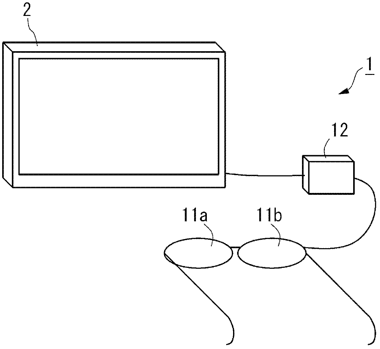
[0048] figure 1 It is a schematic perspective view showing a schematic configuration of the stereoscopic image recognition device (stereoscopic display device) of the first embodiment. figure 1 The stereoscopic image recognition device 1 of the present embodiment shown includes a pair of shutter elements 11a, 11b and a drive unit 12 that drives the shutter elements 11a, 11b.

[0049] A pair of shutter elements 11a, 11b corresponds to the average distance between human eyes, and is arranged in a direction with a predetermined position, for example, figure 1 The configuration shown is in the shape of glasses.

[0050] The drive unit 12 supplies predetermined drive voltages to the shutter elements 11 a and 11 b in synchronization with the image display timing of the image display device 2 . The driving unit 12 supplies, for example, a rectangular wave voltage having a driving frequency of 1000 Hz to the shutter elements 11a and 11b. As for the drive voltage, for example, the o...

no. 2 Embodiment approach

[0088] Figure 17 It is a schematic perspective view showing a schematic configuration of a stereoscopic image recognition device (stereoscopic display device) according to the second embodiment. also, Figure 18 is a schematic side view showing the structure of the stereoscopic image recognition device. The stereoscopic image recognition device 101 of this embodiment shown in each figure is configured to include an optical compensation plate 110, a pair of shutter elements 111a, 111b, and a drive unit 112 for driving the shutter elements 111a, 111b.

[0089] It is assumed that the stereoscopic image recognition device 101 of the second embodiment is used in combination with an image display device 102 that emits linearly polarized light as light used for image formation. Such as Figure 18 As shown, the image display device 102 of this embodiment is a liquid crystal display device configured to include a pair of polarizers 102a and 102b and a liquid crystal panel 102c inte...


PUM

PropertyMeasurementUnit
angleaaaaaaaaaa
transmittivityaaaaaaaaaa

Abstract

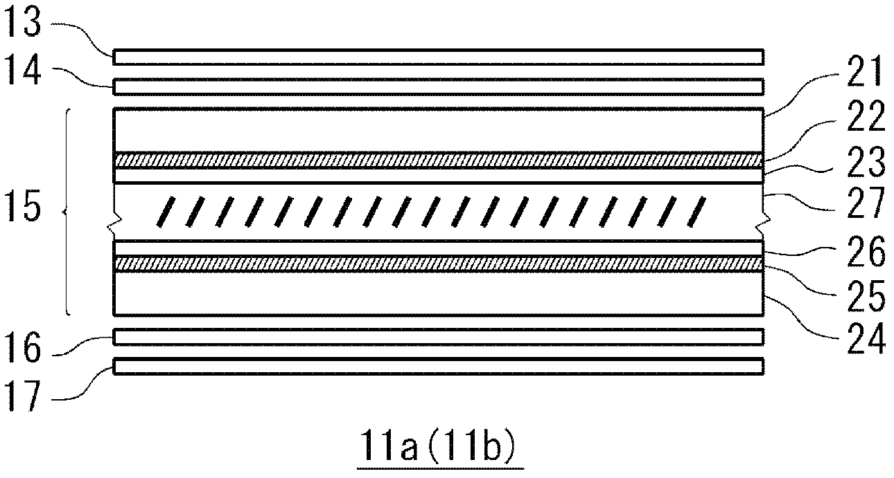
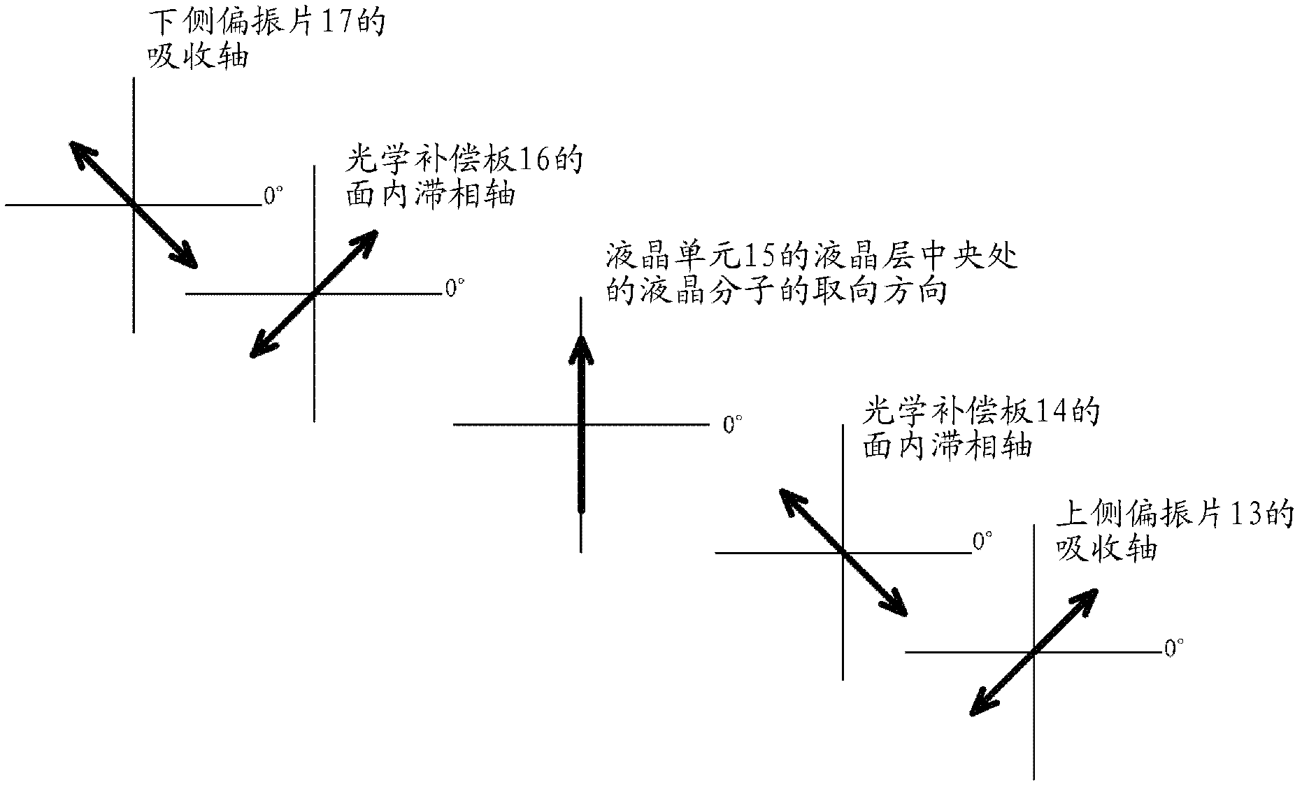
The invention provides a technology by which a user is enabled to visually identify a stereo image without depending on the visual angle in a good condition with excellent opacity and crosstalk prevention. A stereo image identifying device comprises a pair of shutter elements, namely, a first shutter element and a second shutter element; and a drive part selectively driving the first shutter element or the second shutter element to operate by corresponding to the switch between a right-eye image and a left-eye image. The first shutter element and the second shutter element respectively comprise a first polarizer and a second polarizer with their absorption shafts generally perpendicularly configured; a liquid crystal element having a liquid crystal layer with liquid crystal molecules perpendicularly or generally perpendicularly oriented when no voltage is applied and equipped between the first polarizer and the second polarizer; and a first optical compensation board having negative double-shaft optical anisotropy and equipped between the first polarizer and the liquid crystal element. The liquid crystal element is configured in a way that the oriented direction of liquid crystal molecules on the generally central part of the thick direction of the liquid crystal layer and the absorption shaft of the first polarizer or that of the second polarizer are at a generally 45-degree angle. The first optical compensation board is configured in a way that a plane-inside sluggish phase axis is generally perpendicular to the absorption shaft of the first polarizer.

Description

technical field [0001] The present invention relates to image display technology for allowing users to experience stereoscopic display. Background technique [0002] Japanese Unexamined Patent Publication No. 5-257083 (Patent Document 1) discloses a stereoscopic display technology using polarized glasses in which polarizers with polarized light directions differing by 90° are aligned to the left and right eyes and bonded together. . In addition, Japanese Patent Laid-Open No. 6-178325 (Patent Document 2) and Japanese Patent Laid-Open No. 2002-82307 (Patent Document 3) disclose stereoscopic display technology using liquid crystal shutter glasses. The left and right images are synchronized to open and close the left and right shutters. [0003] However, in the conventional example represented by Patent Document 1, a right image and a left image are formed for every other pixel column on the liquid crystal panel, so there is a problem that the resolution of the displayed image...

Claims


Application Information

Patent Timeline
Patent Type & Authority Applications(China)
IPC IPC(8): G02B27/26G02F1/13363H04N13/00G02B30/25
Inventor 岩本宜久都甲康夫
Owner STANLEY ELECTRIC CO LTD
Learn More