Removable heat shield for cooling/heating unit

a heat shield and cooling/heating unit technology, applied in space heating and ventilation, lighting and heating apparatus, heating types, etc., can solve the problems of consuming substantial amounts of electricity, constant heat and sunlight, and running an air conditioner on hot sunny days, etc., to achieve convenient installation, reduce the effect of heat loss and low manufacturing cos

Inactive Publication Date: 2005-02-03
SCISSOM JAY DWIGHT
View PDF10 Cites 16 Cited by
  • Summary
  • Abstract
  • Description
  • Claims
  • Application Information

AI Technical Summary

Benefits of technology

[0025] An advantage of the present invention is that it can be easily installed.
[0026] Another advantage of the present invention is that it can be positioned for best shading relative to the path of the sun.
[0027] An additional advantage of the present invention is that it dissipates the heat.
[0028] One more advantage of the present invention is inexpensive to manufacture.
[0029] Yet another advantage of the present invention is that it can be removed during the cooler seasons and stored.
[0030] Still another advantage of the present invention is that it may reduce electricity consumption by as much as 50%.

Problems solved by technology

However, because the unit is located outdoors, it is constantly being subjected to heat and sunlight.
The heat and energy generated by the sun's rays impede the heat transfer rate from the compressor to the atmosphere resulting in less efficient cooling of the building interior.
Running an air conditioner on hot sunny days consumes substantial amounts of electricity.
Most of the prior art devices involve structures that are more permanent roof or shelter type installations, which do not lend themselves to easy annual installation and removal.
Most of the prior art devices are reflective and deflecting in function but do not provide heat dissipation.

Method used


Image

  • Removable heat shield for cooling/heating unit
  • Removable heat shield for cooling/heating unit
  • Removable heat shield for cooling/heating unit

Examples


Embodiment Construction

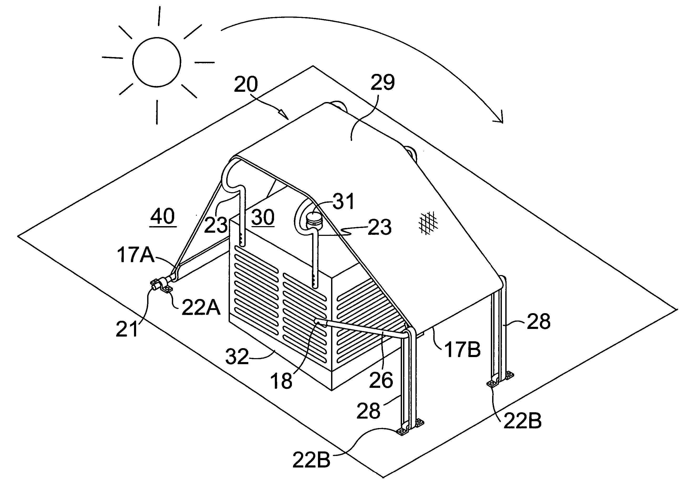
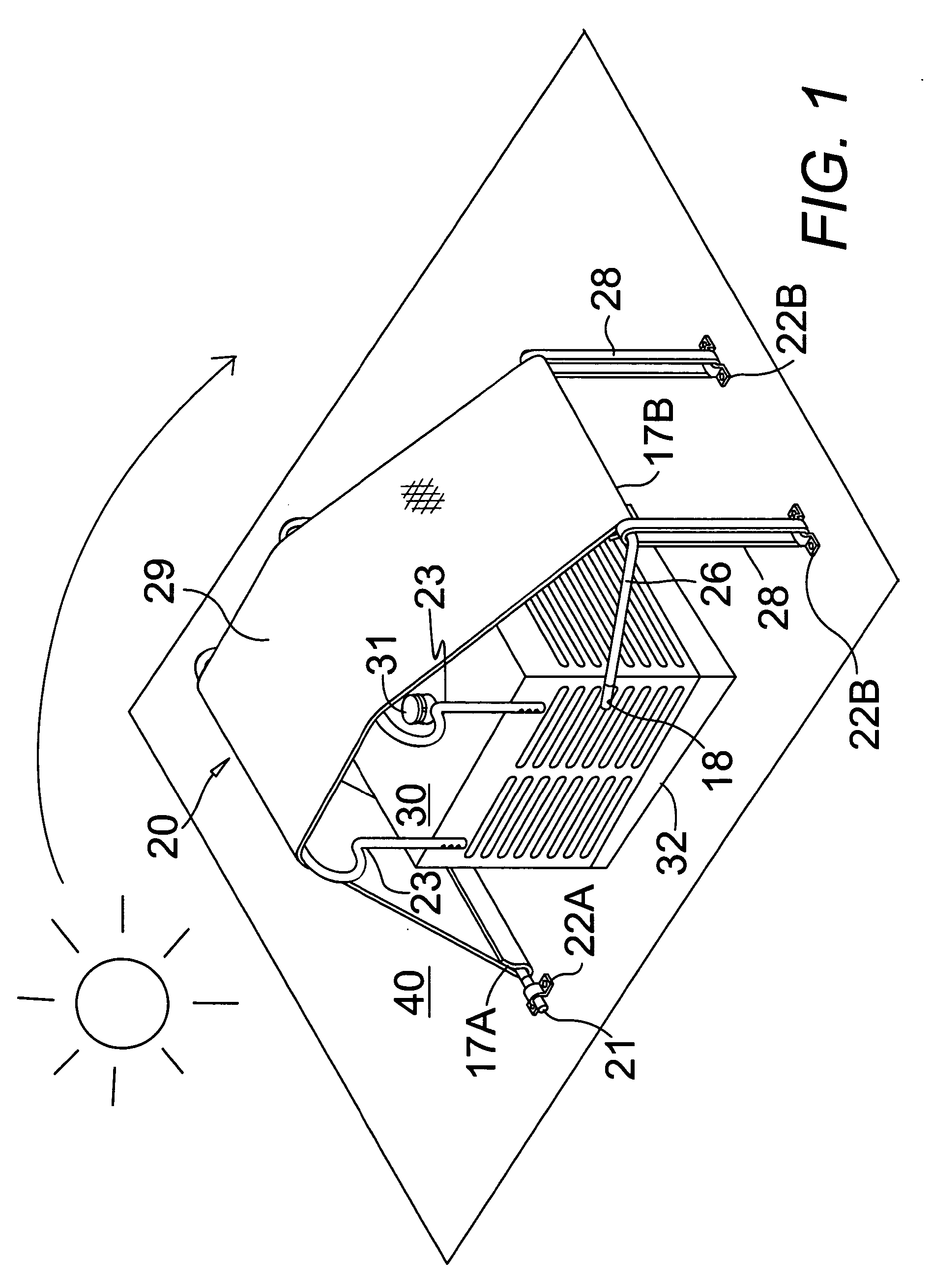
[0037] In FIG. 1-3, a removable heat shield device 20 for a cooling / heating unit 30 with a top vent 31 positioned in a housing outdoors comprises a heat dissipating shading sheet 29 stretched over the unit on an adjustable removable frame system. A first anchoring frame comprises a first rigid elongated anchoring rigid rod element 21 attachable by brackets 22A to an external surface, such as a roof 40, in line with and spaced apart from a base 32 on the side of the housing of an outdoor cooling unit 30. The heat dissipating and shading sheet 29 has a first loop of material 17A at the first end across the width of the sheet 29 with the rigid rod 21 of the inserted through the first loop of material 17A.

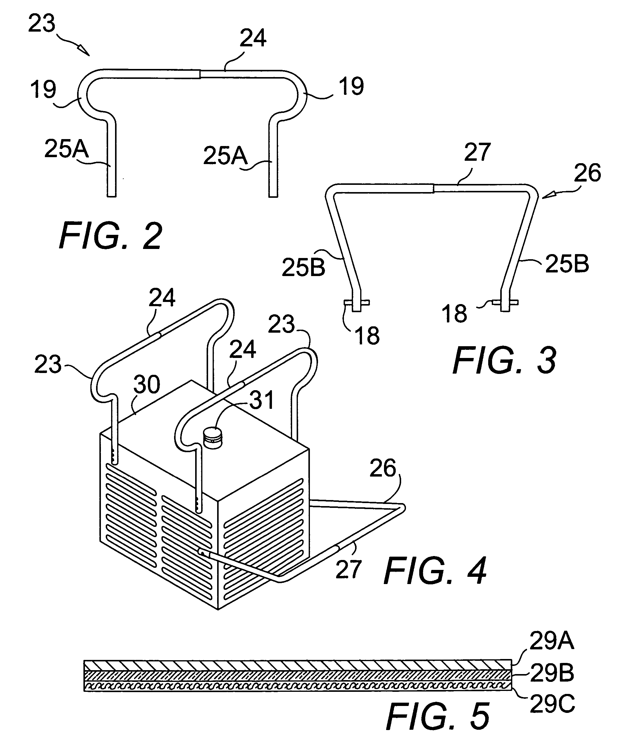
[0038] The device 20 also comprises adjustable elevating frames 23, shown in FIG. 2, which attach to the housing of the outdoor cooling unit 30. Each of the adjustable elevating frames 23 comprise a rigid elongated elevating element 24 positioned apart from and above the housing of an...


PUM


Abstract

A removable heat shield is disclosed for a combined cooling and heating unit, which can be easily installed and removed seasonally. The heat shield has adjustable frame members that can be installed on any type of unit, which can be positioned for best shading as needed for the prevailing building orientation relative to the path of the sun. The heat shield also comprises a covering that can be stretched over an easily the installed framework, which provides instantly attachable and removable heat dissipating shade. The covering may be a three layered heat dissipating covering with a bottom canvas layer for strength, a middle insulating layer, and a top heat dissipating material layer. The heat shield further comprises a tie down means that is capable of stretching and maintaining the heat dissipating and shading sheet in a taut condition.

Description

BACKGROUND OF THE INVENTION [0001] 1. Field of the Invention [0002] The present invention relates to a cover for an air conditioner or swamp cooler, and more specifically, a removable heat shield structure for an outdoor cooling unit or combination heating and cooling unit designed to shield it from sunlight without restricting airflow thereto, which cover is easy to install and remove on a seasonal basis and can be positioned as desired to provide proper shading. [0003] 2. Description of the Prior Art [0004] Conventional outdoor air conditioning units typically include a housing having a compressor, condenser and various other components therein. A fan is also disposed within the housing and operates simultaneously with the compressor to assist in heat removal therefrom. However, because the unit is located outdoors, it is constantly being subjected to heat and sunlight. The heat and energy generated by the sun's rays impede the heat transfer rate from the compressor to the atmosph...

Claims


Application Information

Patent Timeline
Patent Type & Authority Applications(United States)
IPC IPC(8): F24F1/00F24F13/20
CPCF24F1/58
Inventor SCISSOM, JAY DWIGHT
Owner SCISSOM JAY DWIGHT
Why Eureka
Try Eureka