Glow plug with integrated pressure sensor and body thereof

A pressure sensor and spark plug technology, applied in the main field of preheating spark plugs, can solve problems such as high cost and interference measurement

Inactive Publication Date: 2008-04-23
SIEMENS VDO AUTOMOTIVE CORP +1
View PDF1 Cites 11 Cited by
  • Summary
  • Abstract
  • Description
  • Claims
  • Application Information

AI Technical Summary

Problems solved by technology

[0007] [07] A disadvantage of the spark plugs of the prior art is therefore that precise mechanical adjustments are necessary during their installation, resulti...

Method used


Image

  • Glow plug with integrated pressure sensor and body thereof
  • Glow plug with integrated pressure sensor and body thereof

Examples


Embodiment Construction

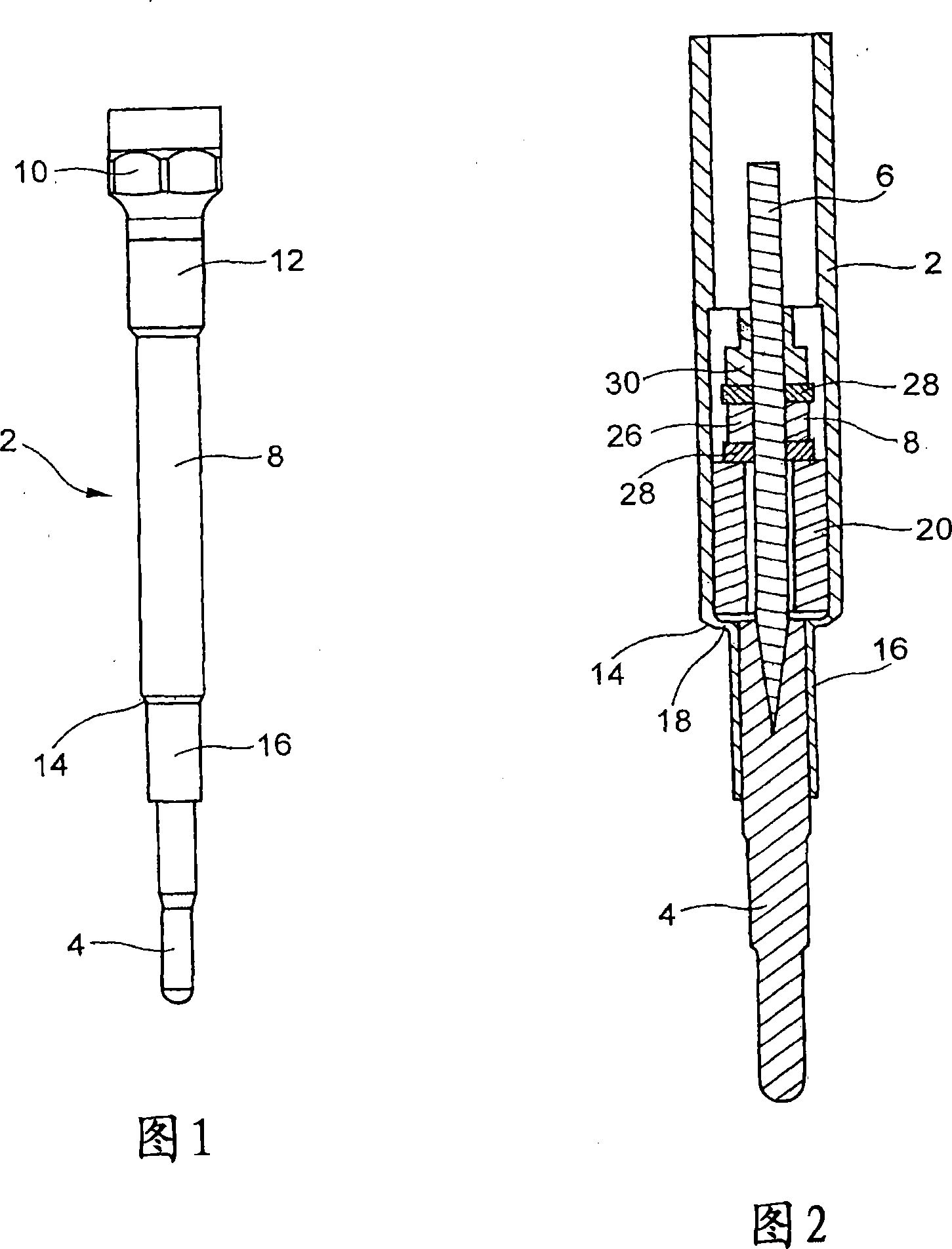
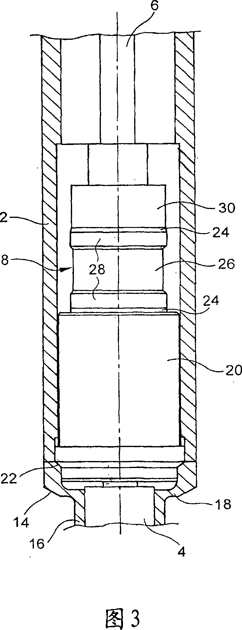
[0027] [27] A glow plug can be seen in Figures 1 and 2, which is known to those skilled in the art and includes a main body 2, a finger body 4, a core (me) 6 and a pressure sensor 8.

[0028] [28] The body 2 is tubular and has a plurality of cylindrical sections. At a first end, referred to as the spark plug tip 10, the spark plug body has a grip area with an outer surface of hexagonal cross-section. This grip area is used to install and remove the glow plugs by tightening / unscrewing them. For mounting, a threaded region 12 is provided adjacent to the spark plug tip 10 . Corresponding threads are provided in the engine cylinder head head to cooperate with the threaded area 12 . In order to improve the sealing between the cylinder head head and the glow plug, it is also conceivable to implement a sealing cone 14 on the main body 2 . This sealing taper 14 will cooperate with a complementary taper surface formed in the cylinder head head and ensure a very good seal between t...


PUM


Abstract

A glow plug includes: a tubular body (2) having at one of its ends a plug head (10) as well as a zone for being fixed into a bore, an arm (4) mounted on the body (2) of the plug at the end opposite to the plug head (10), and secured to the body (2) in a linking zone (16), an elastically deformable portion (18), located between the linking zone (16) with the arm (4) and the zone fixing the plug body (2), such that the linking zone (16) is mobile and can move longitudinally relative to the so-called stationary fixing zone, and a pressure sensor (8) arranged between an element (30) secured to the linking zone (16) and a fixed element (20) of the plug.

Description

technical field [0001] [01] The present invention relates to glow plugs of the integrated pressure sensor type and to bodies of such glow plugs. Background technique [0002] [02] In an internal combustion engine, in particular a Diesel internal combustion engine, each cylinder includes a glow plug for heating the interior of the respective combustion chamber, especially during engine start-up. The glow plug is positioned in a threaded bore through the head of the engine cylinder head. Said glow plug thus comprises a threaded body adapted to be mounted in a corresponding bore in the cylinder head head, and a finger body inside which a glow electrode is housed. [0003] [03] It is likewise known to integrate a pressure sensor with a said glow plug. In fact, it has been noted that knowledge of the value of the internal pressure of each cylinder enables better control of the course of the engine's central combustion. Said information can thus be used to adjust the injection ...

Claims


Application Information

Patent Timeline
IPC IPC(8): G01L23/22F23Q7/00F02N19/04
CPCG01L23/222F23Q2007/002F23Q7/001F02P19/028F02P19/02G01L23/22G01L23/00
Inventor A·拉蒙J·伯罗斯S·戈雷蒂C·帕特里L·贝雷塔
Owner SIEMENS VDO AUTOMOTIVE CORP
Why Eureka
Try Eureka