
Elevator system

An elevator system and elevator car technology, applied in the elevator field, can solve problems such as forced deceleration device action on difficult terminal floors, and achieve the effect of safety diagnosis

Inactive Publication Date: 2012-05-23
HITACHI LTD +1
View PDF0 Cites 0 Cited by
  • Summary
  • Abstract
  • Description
  • Claims
  • Application Information

AI Technical Summary

Problems solved by technology

For this reason, in diagnosis, it is difficult to actually operate the forced deceleration device on the terminal floor

Method used


Image

  • Elevator system
  • Elevator system
  • Elevator system

Examples


Embodiment Construction

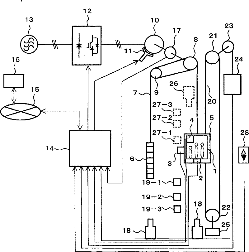
[0016] The following reference figure 1 The structure and general operation of an embodiment of the present invention will be described. As shown in the figure, the elevator car 5 is provided with an elevator car room 1 for passengers, a load sensor 2 for counting the number of passengers, a position detector 3 for detecting the absolute position of the elevator car, and a When the characteristic test is performed, the display 4, etc., which informs passengers to leave the elevator car. The elevator car 5 and the counterweight 6 are connected by a main sling 7, and are suspended on a sheave 8 and a steering pulley 9 that transmit driving force to the moving body. The rotational driving force of the driving device composed of the electric motor 10 and the brake 11 for braking is transmitted to the sheave 8.

[0017] The brake 11 generates a braking force, which is used as a stopping holding force to prevent the elevator car 5 from moving due to the unbalanced force between it and...


PUM


Abstract

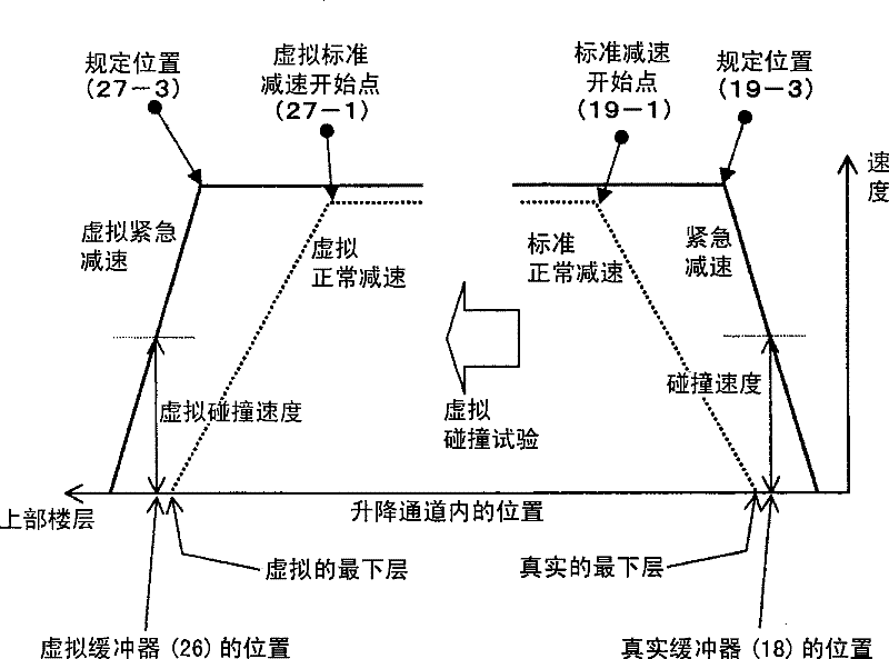
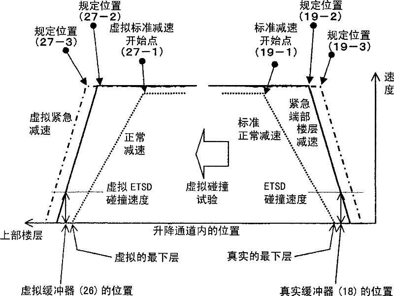
The invention relates to an elevator system. A virtual buffer is arranged at the non-end floor in the lifting channel. The elevator is broken emergently from a predetermined position so as to collect the speed, position and time for passing through and other information of the elevator cage during the deceleration process. Besides, the elevator is collided with the virtual buffer so as to test and validate a series of deceleration data such as the detection of the deceleration starting position, the action of the brake and the adherence of the rope wheel and the suspension cable. The reliability of the brake system of the elevator which is arranged inside a department and an office building is very important, so the actual action and performance of the elevator are examined regularly and frequently in a mode of without damaging the device. The whole brake process of the elevator brake system, ending when the elevator cage is actually stopped, is regularly examined in a mode of without damaging the device.

Description

Technical field [0001] The present invention relates to an elevator, in particular to an elevator system suitable for confirming the braking performance of the elevator. Background technique [0002] In an elevator system, when multiple faults occur at the same time, which is rare, the possibility of a collision between the moving body and the end of the hoistway cannot be ruled out. In order to take countermeasures in the event of the above-mentioned situation, a buffer is set at the bottom of the lifting channel to buffer the moving body and make it stop slowly and safely. This kind of buffer is installed at the bottom of the hoistway. It is set according to the speed and load specifications of the elevator, so that when the moving body collides at a speed exceeding the specified value of the rated speed under the rated load, it can also decelerate at the required speed. To bear the moving body. Based on the fact that in a very fast elevator, the total length of the buffer wi...

Claims


Application Information

Patent Timeline
Patent Type & Authority Patents(China)
IPC IPC(8): B66B5/00
Inventor 稻叶博美井上秀树吉川敏文大西友治大宫昭弘小笠原刚寺本律萩原高行
Owner HITACHI LTD
Learn More