
Method and system for reading RFID tags

A radio frequency identification tag, radio frequency identification technology, used in instruments, inductive record carriers, computer parts and other directions

Inactive Publication Date: 2010-09-15
IND TECH RES INST
View PDF6 Cites 0 Cited by
  • Summary
  • Abstract
  • Description
  • Claims
  • Application Information

AI Technical Summary

Problems solved by technology

This system solves the problems of clock recovery, synchronization and data frame decoding of noisy signals from printed RFID tags

Method used


Image

  • Method and system for reading RFID tags
  • Method and system for reading RFID tags
  • Method and system for reading RFID tags

Examples


Embodiment Construction

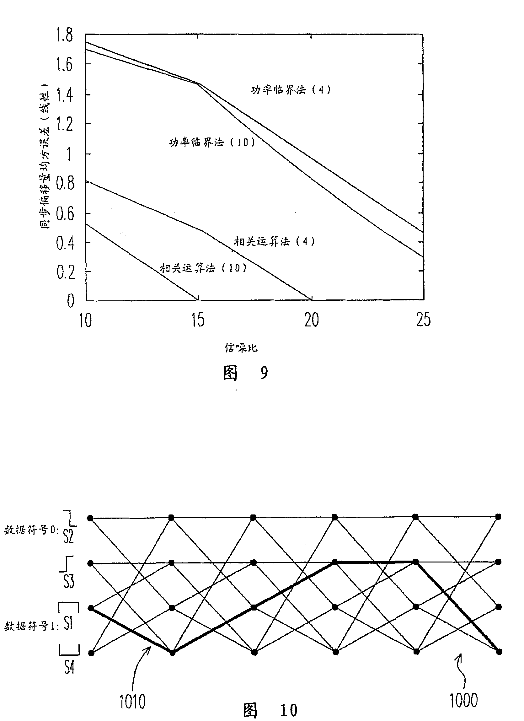
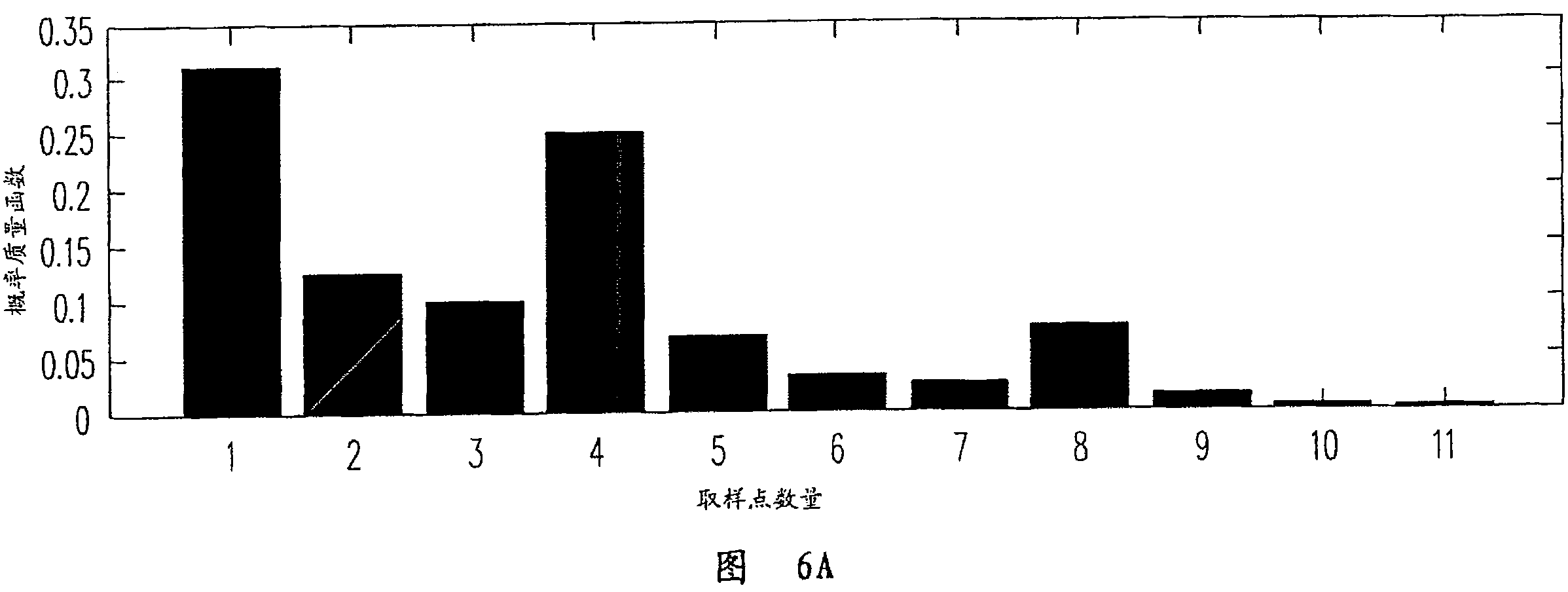
[0048] In a typical tag signal, an RFID tag transmits data continuously and repeatedly. The label data for each repetition is included in the data frame. Instead, each data frame is guided by leading data. Each leading data and data frame contains multiple symbols. Figure 4 It is a key flow chart of a method for reading a radio frequency identification tag according to an embodiment of the present invention. First, a tag signal is received from an RFID tag (ie, step 410), and then the data clock rate of the tag signal is restored (ie, step 420). When the data clock rate is identified, a synchronization step is performed to calculate the position of the frame synchronization point between the preamble and the data frame following the preamble (ie step 430). This frame synchronization point is the point where the leading data ends and the data frame begins. After identifying the data clock rate and frame synchronization point, the process proceeds to decode the data frame a...


PUM


Abstract

A method and a system for reading radio frequency identification (RFID) tags are provided. The method includes the following steps. First, receive a tag signal from the RFID tag. Recover a data clock rate from the tag signal according to statistics of pulse lengths of the tag signal. Next, determine a frame synchronization point of a data frame following a preamble in the tag signal by a signal correlation between the preamble and a predetermined signal pattern according to the data clock rate. Finally, decode the data frame by using an adaptive Viterbi algorithm on an extended trellis diagram. The extended trellis diagram includes a plurality of nodes and a plurality of branches connecting the nodes. The nodes and the branches are arranged according to the modulation scheme of the data frame and possible variations of the data clock rate.

Description

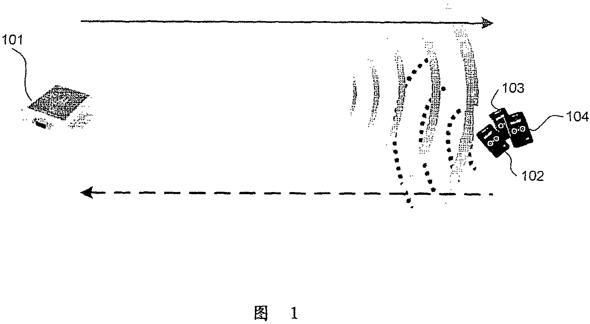
technical field [0001] The present invention relates to a method and system for reading radio frequency identification tags (RFID tags for short), and in particular to a method and system for reading printed radio frequency identification tags (printed RFID tags). Background technique [0002] figure 1 A conventional RFID reader 101 is shown with three RFID tags 102-104. The reader 101 emits ultra high frequency (UHF) or high frequency (high frequency, HF) electromagnetic waves to enable the tags 102-104, so that the tags 102-104 can backscatter (backscatter) tag signals to the reader 101 . The data sent by the RFID tag is modulated in this tag signal. In order to detect data, the RFID tag reader must receive the tag signal and then generate the above data based on the tag signal. This data generation process is known as signal detection, decoding or demodulation. [0003] For example, the RFID tags 102-104 may use an FMO modulation scheme to encode data. figure 2 The...

Claims


Application Information

Patent Timeline
Patent Type & Authority Patents(China)
IPC IPC(8): G06K7/016G06K7/08
Inventor 林志鸿余佳任陈俊才
Owner IND TECH RES INST
Learn More