uhf frequency band passive rfid high separation dual frequency transceiver splitter

A technology of transceiver splitter and separation degree, applied in the field of radio frequency identification, to achieve the effect of competitiveness, convenient adjustment and easy realization

Inactive Publication Date: 2011-12-28
SOUTH CHINA UNIV OF TECH
View PDF0 Cites 0 Cited by
  • Summary
  • Abstract
  • Description
  • Claims
  • Application Information

AI Technical Summary

Problems solved by technology

[0004] The separation degree of the general circulator or directional coupler used in the existing transceiver separation technology generally only reaches about 30db, which cannot meet the needs of RFID technology, and a high-isolation co-frequency transceiver splitter must be designed
[0005] At present, there is a microstrip UHF frequency band RFID reader transceiver splitter, which can achieve 60db transceiver isolation, but it can only be realized on a single frequency band (Wan-Kyu Kim, Moon-Que Lee, Jin-Hyun Kim, et al ,A PassiveCirculator with High Isolation using a Directional Coupler for RFID,Proceeding of the 36 th European Microwave Conference, pp 196-199, 2006)

Method used


Image

  • uhf frequency band passive rfid high separation dual frequency transceiver splitter
  • uhf frequency band passive rfid high separation dual frequency transceiver splitter

Examples


Embodiment Construction

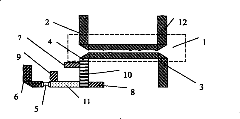
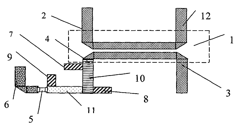
[0018] like figure 1 As shown in the figure, due to the limitation of machining accuracy of ordinary microstrip coupled line directional coupler 1, the isolation between transmitter port 2 and receiver port 3 is not high, and part of the input signal of transmitter port 2 will leak into receiver port 3 go. In order to eliminate this part of the leakage, a load with an appropriate impedance value is designed in the load port 4 to reflect a part of the energy to the receiver port 3. When the reflected signal is equal in magnitude and opposite in phase to the leakage signal, the leakage signal is cancelled. In this way, the complete separation of the transmitted signal and the received signal is realized. In order to achieve high separation at both frequencies, it is required that the load can produce the required amplitude and phase reflection at both frequencies, that is, the load impedance can reach the required impedance value at both frequencies . For this reason, the pre...


PUM


Abstract

The invention discloses a UHF frequency band passive RFID high-separation dual-frequency transceiver separator, which includes a microstrip coupling line directional coupler, a transmitter port, a receiver port, a load port and an antenna port, and is characterized in that it also includes an absorption resistor, a micro One of the strip line segments, the second of the microstrip line segment, one of the open branch lines, the second of the open circuit branch lines, the third of the open circuit branch lines and the microstrip open line, one end of one of the microstrip line segments and one end of one of the open circuit branch lines Connected to the load port, the other end of one of the microstrip line segments is connected to one end of the open circuit branch line two and one end of the microstrip line segment two, the other end of the microstrip line segment two is connected to one end of the open circuit branch line three and the absorption resistor One end of the snubber resistor is connected to one end of the microstrip open line. The invention can simultaneously realize the high-separation separation of RFID transceiving signals on two frequency bands, and improve the working distance of the RFID reader-writer.

Description

technical field [0001] The invention relates to the technical field of radio frequency identification, in particular to a UHF frequency band passive RFID high-separation dual-frequency transceiver splitter. Background technique [0002] Radio frequency identification technology is a technology that uses radio frequency technology to realize automatic identification of objects. The radio frequency identification system mainly includes two parts: a reader and an electronic tag. The electronic tag is attached to the object and contains a unique ID number and item information. , the reader is used to read the information on the electronic tag, so as to realize the automatic identification of the object. When the radio frequency identification system is working, the reader sends a radio frequency signal through the antenna. After receiving the read and write instructions from the reader, the electronic tag returns the radio frequency signal to respond, and transmits the ID number...

Claims


Application Information

Patent Timeline
Patent Type & Authority Patents(China)
IPC IPC(8): G06K7/00H01Q1/22
Inventor 谢泽明赖晓铮李文彩
Owner SOUTH CHINA UNIV OF TECH
Why Eureka
Try Eureka