Method and apparatus for creating a borehole in the ground

A soil and drill pipe technology, applied in drilling equipment and methods, earth-moving drilling, drilling with mechanical conveying devices, etc. Achieve the effect of good force distribution and high cutting ability

Inactive Publication Date: 2008-06-18
BAUER MASCH GMBH
View PDF1 Cites 16 Cited by
  • Summary
  • Abstract
  • Description
  • Claims
  • Application Information

AI Technical Summary

Problems solved by technology

[0006] However, when drilling with double ends, the result is in certain cases only a relatively low drilling progress, often accompanied by high wear on the inner wall of the drill pipe and on the auger

Method used


Image

  • Method and apparatus for creating a borehole in the ground
  • Method and apparatus for creating a borehole in the ground
  • Method and apparatus for creating a borehole in the ground

Examples


Embodiment Construction

[0042] In Figures 6 to 14, the auger is not shown for clarity. Elements having the same effect are marked with the same reference numerals in all figures.

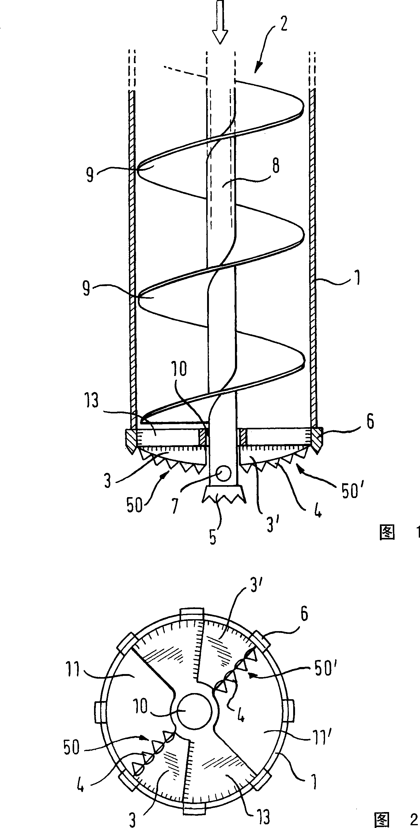
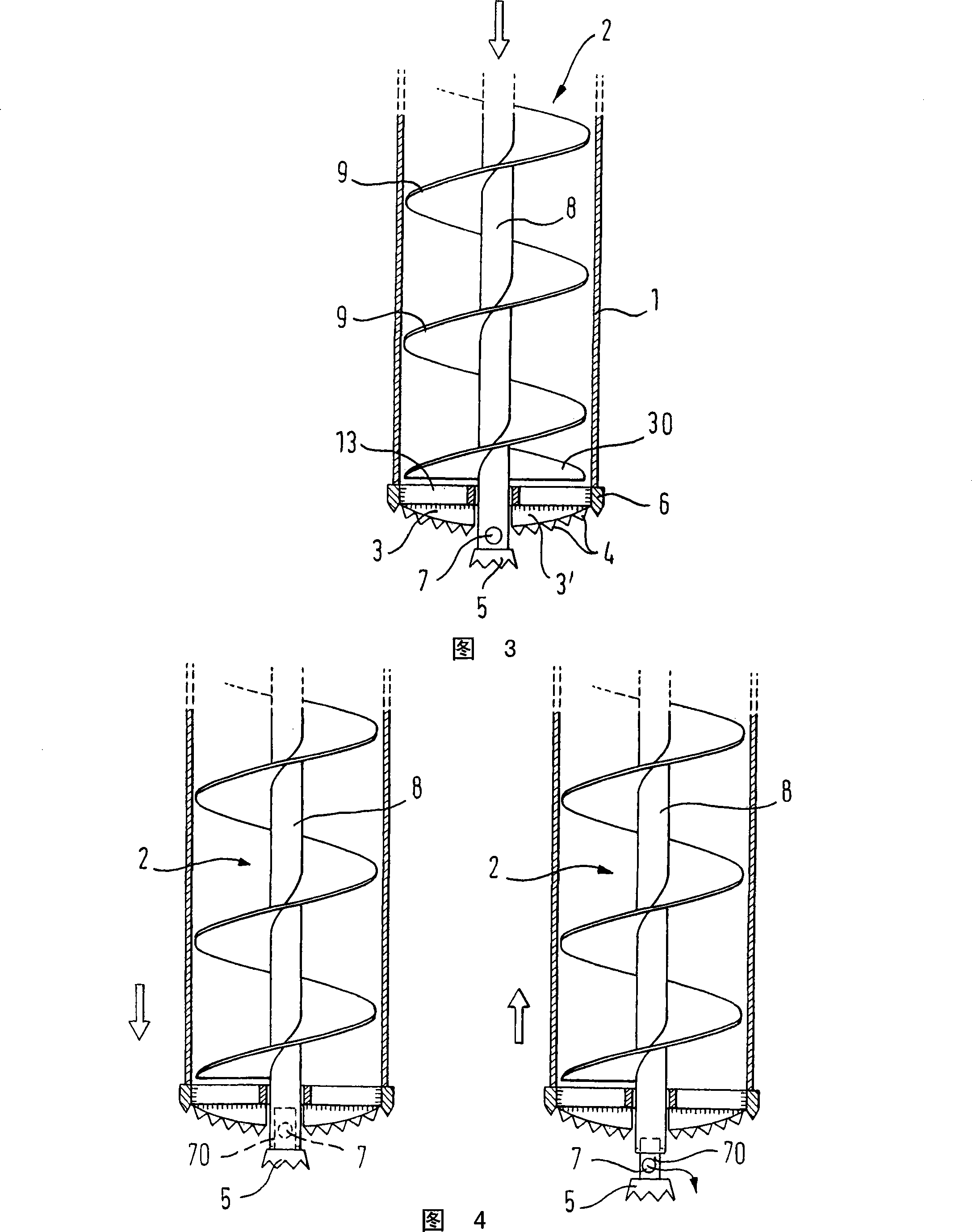
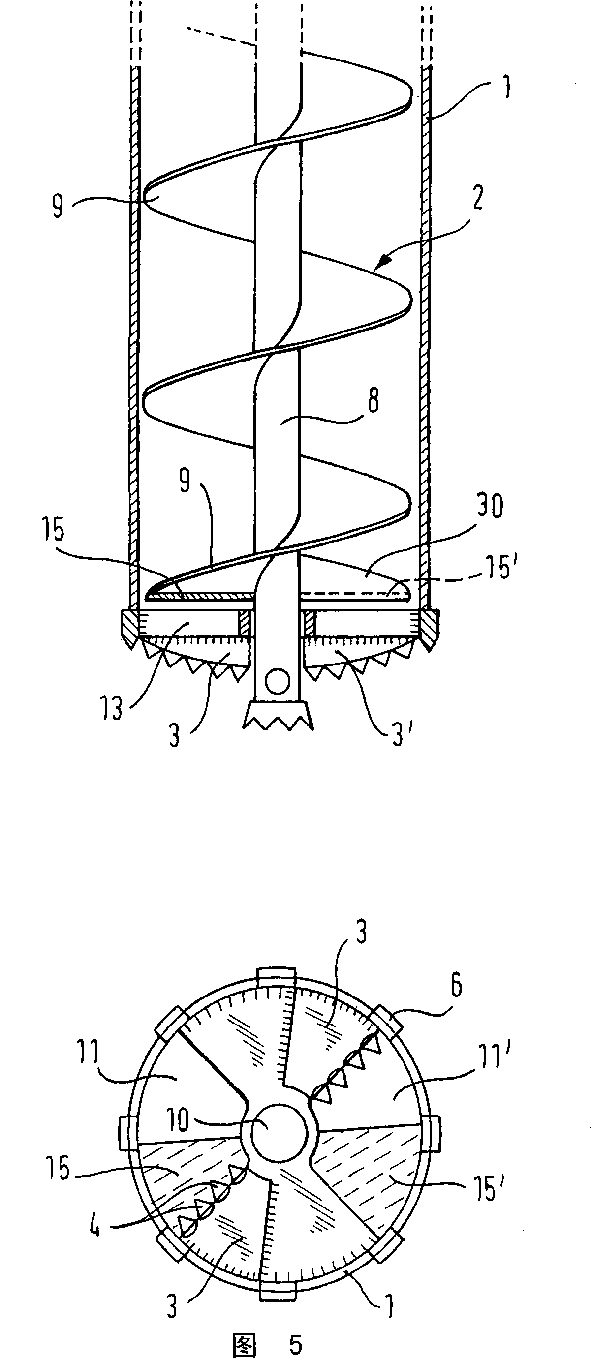
[0043] Figures 1 and 2 show a first embodiment of a device for producing boreholes in soil according to the invention. The device comprises a rotatably driven drill rod 1 , wherein a screw conveyor 2 is arranged coaxially. The screw conveyor 2 has a core tube 8, on the outside of which a screw flight 9 extends longitudinally.

[0044] At the end of the drill rod 1 facing the borehole, a drill tool holder 13 designed as a cover plate covers the drill rod 1 to some extent. The drill holder 13 extends radially in section from the wall of the drill rod 1 to the longitudinal axis of the drill rod 1 . On the drill holder 13, 2 openings 11, 11' in the shape of a sector are formed to allow the material to be transported through the drill holder 13 towards the inside of the drill pipe and the conveying part of the screw conveyor...


PUM


Abstract

The invention relates to a method for producing a borehole in the soil, in which a drill pipe and a conveyor screw arranged inside the drill pipe are set into rotation and introduced into the soil, and in which outcropping soil material is loosened by means of at least one main cutting edge, which is positioned axially in front of the conveyor screw, and is conveyed by means of the conveyor screw in the inside of the drill pipe. In accordance with the invention provision is made for the main cutting edge to be arranged on the drill pipe and to be rotated therewith. The invention further relates to a device for producing a borehole in the soil which can be employed in the method according to the invention.

Description

[0001] The invention relates to a method for producing boreholes in soil according to the preamble of claim 1 . In this method, it is provided that the drill pipe and the auger arranged inside the drill pipe are arranged to be rotated and introduced into the soil, and it is provided that the soil material outcropping is loosened by at least one main cutting edge and conveyed by the auger inside the drill pipe The tool is transported away, the main cutting edge is located axially in front of the screw conveyor. [0002] The invention also relates to a device for producing boreholes in soil according to the preamble of claim 5, comprising a drill rod, an auger arranged inside the drill rod and at least one main cutting edge axially positioned in the helical The conveyor was previously used to strip soil material. Background technique [0003] Drilling can be used, inter alia, for making foundation elements and / or for building up walls. [0004] Methods and devices for casing s...

Claims


Application Information

Patent Timeline
Patent Type & Authority Applications(China)
IPC IPC(8): E21B7/00E21B10/44E21B17/22
CPCE21B10/44E21B7/005
Inventor G·施瓦布
Owner BAUER MASCH GMBH
Why Eureka
Try Eureka