
Light diffusing plate and lighting device using it

一种光扩散板、照明装置的技术,应用在照明装置、照明装置的零部件、照明和加热设备等方向,能够解决生产性下降、光源正上方暗、难以实现轻量化等问题,达到高亮度化、消除亮度不匀的效果

Inactive Publication Date: 2008-06-25
IDEMITSU KOSAN CO LTD
View PDF5 Cites 9 Cited by
  • Summary
  • Abstract
  • Description
  • Claims
  • Application Information

AI Technical Summary

Problems solved by technology

[0010] However, in the assembly process of the liquid crystal backlight, there is a problem that the prism sheet must be assembled with two other optical functional films (light diffusing film, polarized light separation film, etc.) according to different situations, so the process is long and difficult. Complicated, the cost of these optical functional films including prism sheets increases, resulting in decreased productivity
Therefore, the problem is that the brightness unevenness is serious when emitting light, and the light emission is uneven.
Among them, in the case where the concavo-convex pattern is an optical element array composed of V-shaped groove prisms with a cross-sectional apex angle of 90°, there is a problem that as the position from the center between the light sources approaches to the position directly above the light source, due to the Total reflection characteristics, the incident light cannot exit (transmit) from the exit surface, on the contrary, it is reflected to the light source side, the brightness is extremely reduced, the darkest is directly above the light source, and the luminescence is uneven, which is difficult to be practical
[0013] In addition, there is also an attempt to form a linear Fresnel lens on the surface (for example, refer to Patent Document 3), but there is a problem that in the case of a linear light source such as a cold cathode tube, although the viewing angle dependence is high, the front brightness is high. And uniform, but when viewed from an oblique direction, the brightness will be extremely reduced, but the shadow of the light source is very obvious
However, although thinning can be achieved with this method, it is difficult to achieve weight reduction due to the use of multiple light guide plates

Method used


Image

  • Light diffusing plate and lighting device using it
  • Light diffusing plate and lighting device using it
  • Light diffusing plate and lighting device using it

Examples


Embodiment

[0124] 0029

[0125] Hereinafter, the specific form of the manufacturing method of the light-diffusion plate in this invention is demonstrated in detail taking the polycarbonate resin of transparent resin as a representative example.

[0126] 1) Preparation of light-diffusing resin composition

manufacture example 1

[0128] As a thermoplastic transparent resin, 100 parts by mass of polycarbonate resin (FN1900A manufactured by Idemitsu Kosan Co., Ltd.) was mixed with bridging propylene beads (PMMA, XX03BZ manufactured by Sekisui Chemical Industry Co., Ltd., average particle size: 100 μm) 5 As a light-diffusing material, it was melted and kneaded at 280° C. in a kneading extruder with a diameter of 40 mm to obtain pellets of a light-diffusing resin composition with a total light transmittance of 93.8%.

[0129] 0030

manufacture example 2

[0131] In the batching of the light-diffusing resin composition of Production Example 1 above, except that bridged propylene beads (MBX-20 manufactured by Sekisui Chemical Industry Co., Ltd., with an average particle diameter of 20 μm) were used as the addition amount of the light-diffusing material as Except for 1 part by mass, particles of a light-diffusing resin composition having a total light transmittance of 93.5% were obtained by the same manufacturing method as in Example 1.

[0132] 0031


PUM

PropertyMeasurementUnit
particle diameteraaaaaaaaaa

Abstract

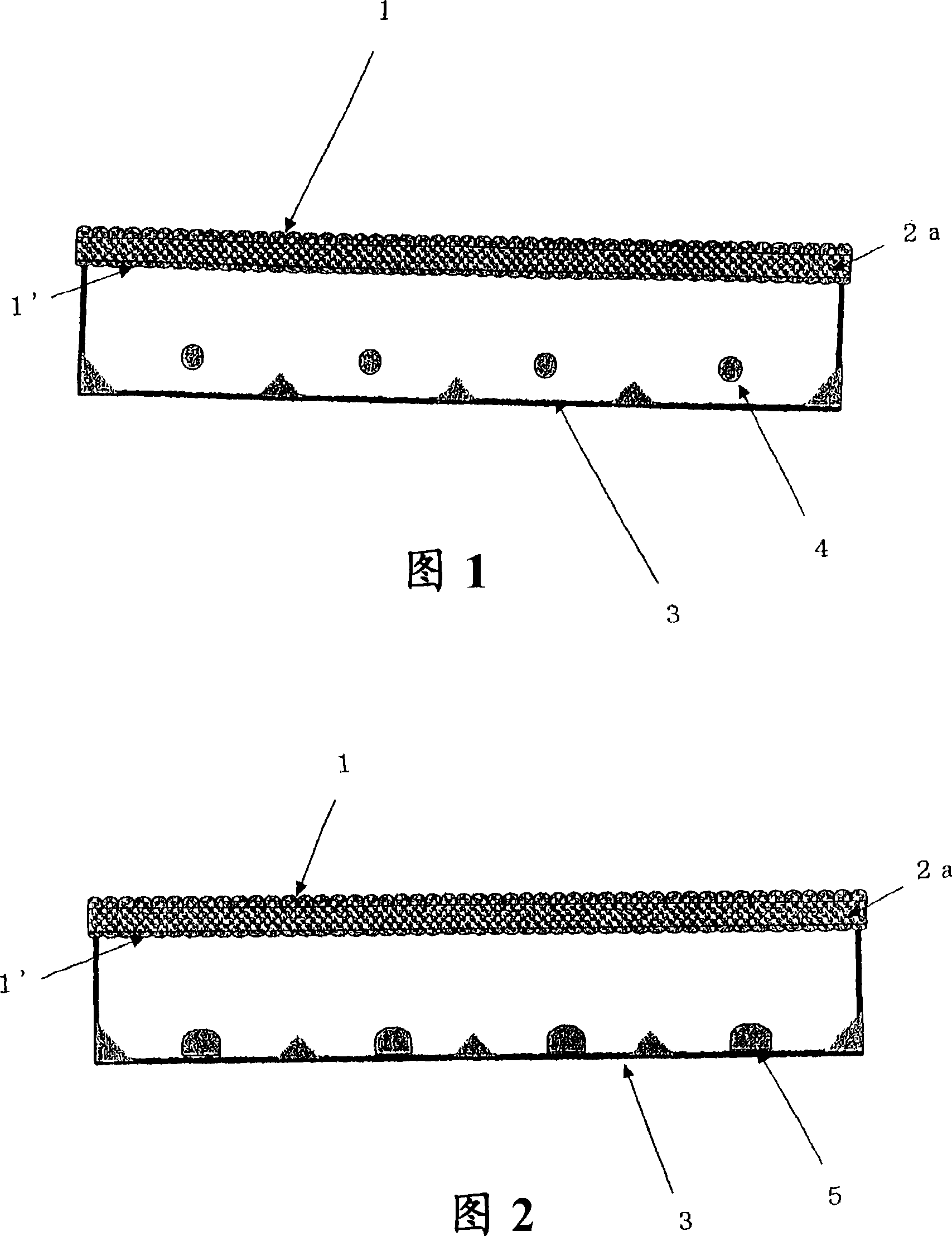
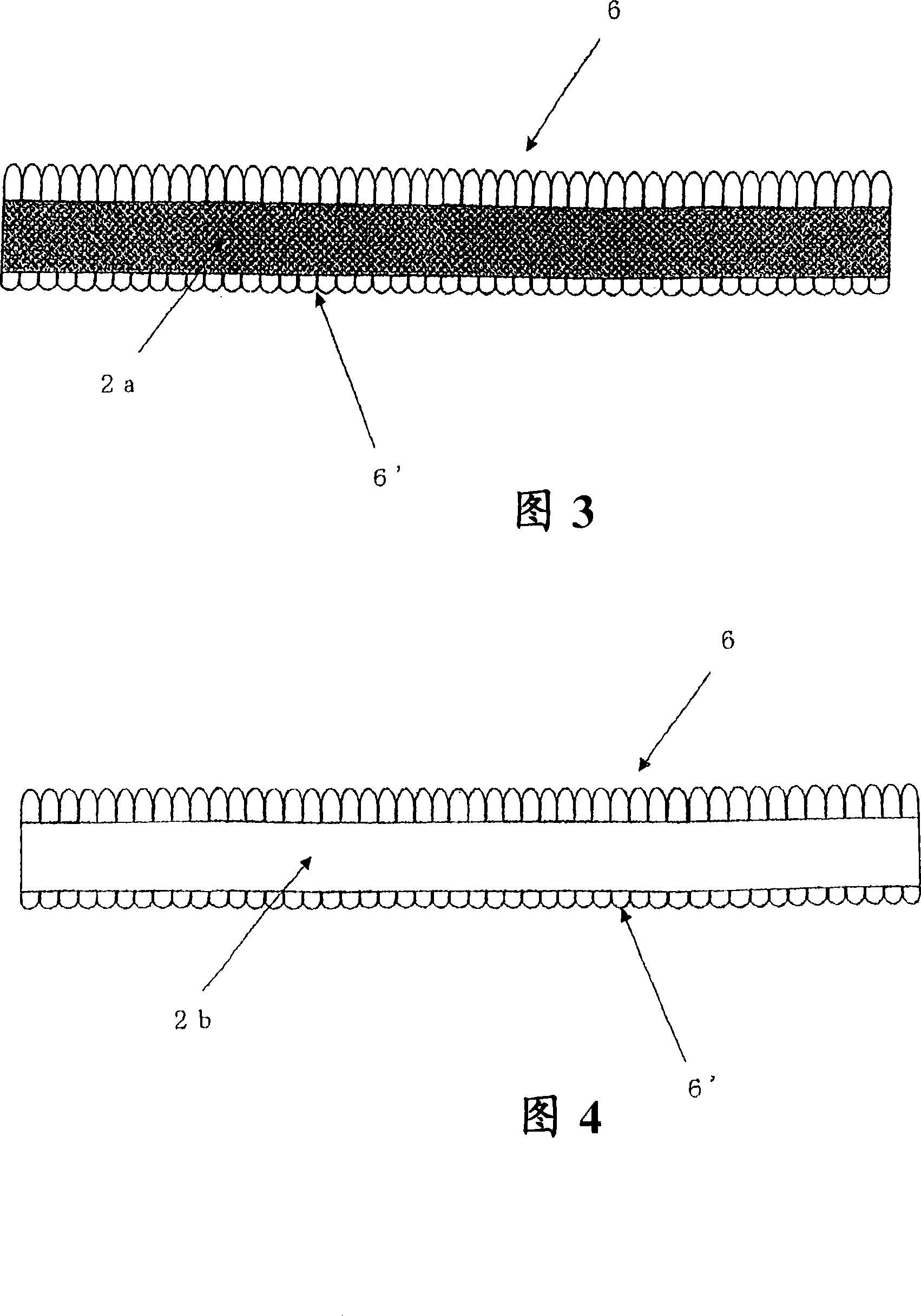
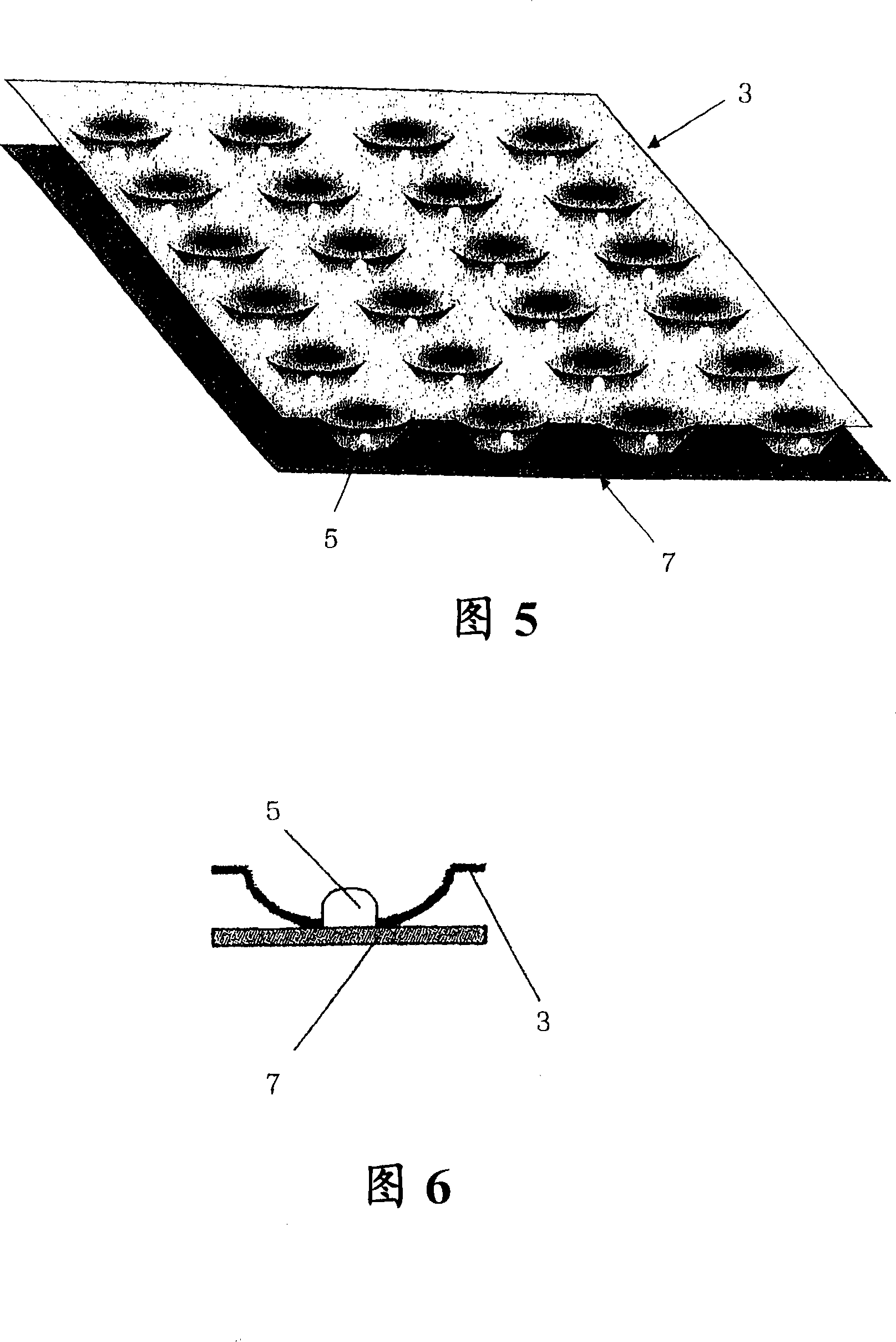
A light diffusion plate (2a) with an optical element array (1, 1′) integrally formed on the front and back, and a box-shaped light reflection plate ( 3) Constructing a direct-type lighting device, thereby providing a light-diffusing plate and a thin direct-type lighting device having the light-diffusing plate, which can eliminate brightness unevenness (uniform brightness) in the number of light sources (distance between light sources) at a practical level ) and achieve high brightness (exhibiting the same brightness as when laminating conventional prism sheets).

Description

technical field [0001] 0001 [0002] The present invention relates to a light diffuser formed by integrally forming an array of optical elements on the front and back, and a direct lighting device configured by placing the light diffuser on a box-shaped light reflection plate provided with a light source inside. . Background technique [0003] 0002 [0004] Conventionally, in order to eliminate the light shadow of the light source (fluorescent tube) of the backlight unit in a liquid crystal display with a large screen, firstly, a light diffusion plate is provided. [0005] The light diffusion plate is required to have the property of dispersing the transmitted light over a wide angle in the traveling direction. [0006] In addition, in order to project transmitted light with high brightness on the entire surface of the liquid crystal module, a light diffusion plate is usually used as a support, and at least one prism sheet is interposed between the light diffusion plate a...

Claims


Application Information

Patent Timeline
Patent Type & Authority Applications(China)
IPC IPC(8): F21S2/00G02B5/02F21V5/04G02F1/13357G02B3/00F21Y101/02G02B3/06F21Y103/00G02F1/1335
CPCG02F1/133504G02B5/0278G02F1/133611G02B5/0215G02B5/0242F21V3/00G02F2001/133607G02B5/0268G02F1/133607G02B5/02G02F1/1335
Inventor 川东宏至木暮真巳
Owner IDEMITSU KOSAN CO LTD
Learn More